Inflatable curtain mounting bracket

a mounting bracket and curtain technology, applied in the direction of pedestrian/occupant safety arrangement, vehicular safety arrangment, vehicle components, etc., can solve the problems of occupant impact on various parts of the vehicle interior, occupant may be ejected from the vehicle, and automotive fatalities, so as to facilitate the installation of the fastener

Inactive Publication Date: 2005-03-03
AUTOLIV ASP INC
View PDF29 Cites 83 Cited by
  • Summary
  • Abstract
  • Description
  • Claims
  • Application Information

AI Technical Summary

Benefits of technology

[0022] The mounting bracket may additionally comprise a first hole and a second hole. The first hole is added to the base bracket and the second hole is added to the retaining clip. Preferably, the first hole and the second hole are sized to receive a fastener. More specifically, the first hole and the second hole are sized such that the fastener may traverse the mounting bracket by passing through the first hole and the second hole. In some embodiments, the holes can be sized and / or constructed such that the size of the first hole differs from the size of the second hole in order to accommodate various build tolerances and allow for easier installation of the fastener.

Problems solved by technology

During a roll-over accident, the vehicle occupants can be jostled considerably, thereby causing the occupant to impact various parts of the vehicle interior.
Even worse, the occupant may be ejected from the vehicle.
Such “occupant excursion” during roll-over accidents is a common cause of automotive fatality, particularly in the case of vehicle occupants that are not wearing a seat belt during the roll-over.
Consequently, when not inflated, the curtain airbag includes a significant amount of airbag material.
Unfortunately, many known mounting brackets have significant disadvantages that have limited the ability of vehicle and airbag manufacturers to implement and use these brackets with airbag systems in which the curtain includes a manifold.
Specifically, most known mounting brackets lack a feature that retains or otherwise holds the manifold in the correct position.
Without such retention, there is an inherent risk that the manifold will flex or otherwise move during deployment.
This movement of the manifold can be extremely detrimental as it can increase the time required to inflate the airbag and / or cause the inflated airbag to become situated in an improper or undesirable position.
While such brackets have represented an improvement in the art, many of these brackets are limited by the fact that they are expensive, costly, and difficult to use.
As a result, if airbag manufacturers choose to employ these brackets, the overall tooling, production, and assembly costs of the airbag system are significantly increased.
Moreover, many mounting brackets that are designed to retain a manifold are further limited in that the system or feature that captures the manifold is often very complicated.
As a result, the process by which an airbag installer captures a portion of the manifold within these complex features is arduous, time-consuming, and labor intensive.
Even working together, it will likely take multiple employees several minutes to install each airbag unit using these known brackets as they will have to position the manifold within the bracket, capture the manifold, and then permanently attach to the bracket and the retained manifold to the vehicle interior.
As the manufacturer incurs costs for every moment that passes during the manufacturing process, these several minutes drastically raise the total production costs and reduce the manufacturer's overall profit margin.
Lastly, many known mounting brackets that retain a manifold have a further limitation in that they may not be used with most secondary brackets.
Unfortunately however, the shape of the most known mounting brackets is incompatible with the shape of these secondary brackets.
As a result, before vehicle manufacturers can employ these mounting brackets, they will first be required to expend additional resources in reconfiguring and / or moving the secondary brackets away from the area occupied by the mounting brackets.

Method used


Image

  • Inflatable curtain mounting bracket
  • Inflatable curtain mounting bracket
  • Inflatable curtain mounting bracket

Examples


Embodiment Construction

[0036] The presently preferred embodiments of the present invention will be best understood by reference to the drawings, wherein like parts are designated by like numerals throughout. It will be readily understood that the components of the present invention, as generally described and illustrated in the figures herein, could be arranged and designed in a wide variety of different configurations. Thus, the following more detailed description of the embodiments of the apparatus, system, and method of the present invention, as represented in FIGS. 1 through 9, is not intended to limit the scope of the invention, as claimed, but is merely representative of presently preferred embodiments of the invention.

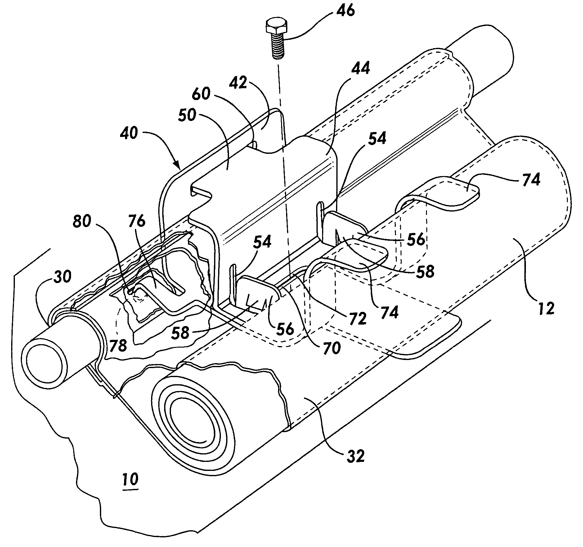
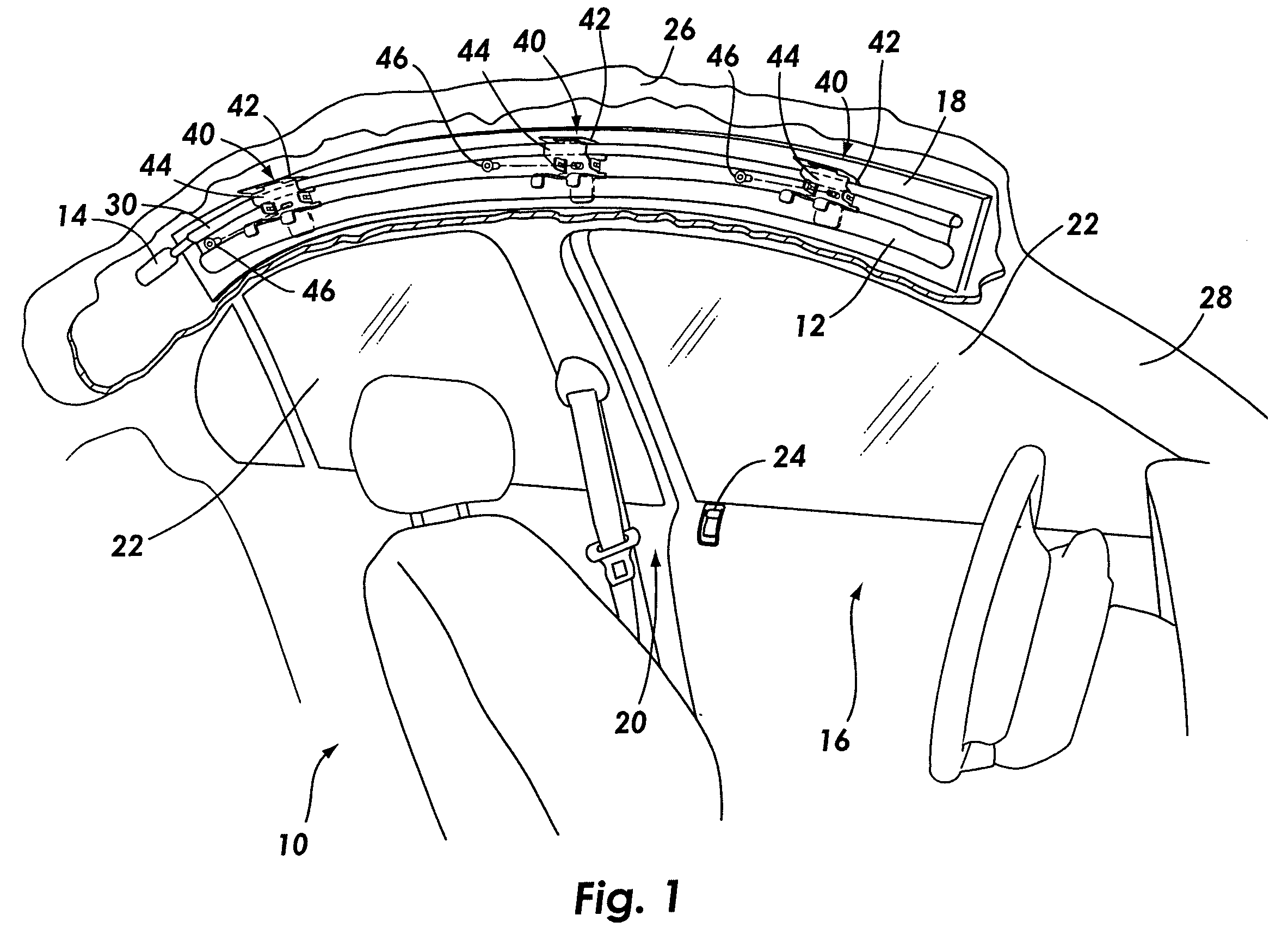
[0037] Referring to FIG. 1, a vehicle interior 10 is depicted with an attached inflatable side curtain airbag 12. The side curtain airbag 12 is attached to an inflator 14 that provides inflation gas to the airbag 12 during an accident. A sensor and / or an ECU (not shown) that provides...


PUM


Abstract

A mounting bracket that may be used to mount an inflatable curtain airbag having a manifold to a vehicle interior is disclosed. The mounting bracket includes a base bracket that has at least one aperture and at least one connecting tab. The mounting bracket also includes a retaining clip that is attachable to the base bracket. The retaining clip has at least one receiving portion and at least one inserting tab. The at least one inserting tab is constructed such that it may be inserted into the at least one aperture. Similarly, the at least one connecting tab is designed to engaged the at least one receiving portion. Preferably, the mounting bracket is constructed such that when the retaining clip is attached to the base bracket, the mounting bracket retains the manifold between the base bracket and the clip.

Description

BACKGROUND OF THE INVENTION [0001] 1. Field of the Invention [0002] The present invention relates to attaching an airbag to the interior of a vehicle. More specifically, the present invention relates to novel mounting bracket that may be used to attach an inflatable curtain airbag having a manifold to an interior vehicle surface. [0003] 2. Description of Related Art [0004] Inflatable airbags are well accepted for use in motor vehicles and have been credited with preventing numerous deaths and injuries. In fact, the inclusion of inflatable safety restraint devices, or airbags, is now a legal requirement for many new vehicles. Airbags are typically installed in the steering wheel and in the dashboard on the passenger side of a car. In the event of an accident, an accelerometer within the vehicle measures the abnormal deceleration and triggers the ignition of a pyrotechnic charge. Expanding gases from the charge fill the airbags, which immediately inflate in front of the driver and pas...

Claims


Application Information

Patent Timeline
Patent Type & Authority Applications(United States)
IPC IPC(8): B60R21/213B60R21/217B60R21/231
CPCB60R21/213B60R21/232B60R21/217
Inventor RHEA, SCOTT L.POWALS, BRIAN
Owner AUTOLIV ASP INC
Why Eureka
Try Eureka