
Pipe joint for refrigeration cycle having combination of O-ring and backup ring

Inactive Publication Date: 2005-03-03
DENSO CORP
View PDF4 Cites 43 Cited by
  • Summary
  • Abstract
  • Description
  • Claims
  • Application Information

AI Technical Summary

Benefits of technology

[0010] In view of the points described above, it is an object of the present invention to provide a pipe joint for a refrigeration cycle in which the first hermetic sealing-member leading to the atmosphere side is formed of a plastic material less permeable to a carbon dioxide refrigerant thereby to minimize refrigerant leakage.
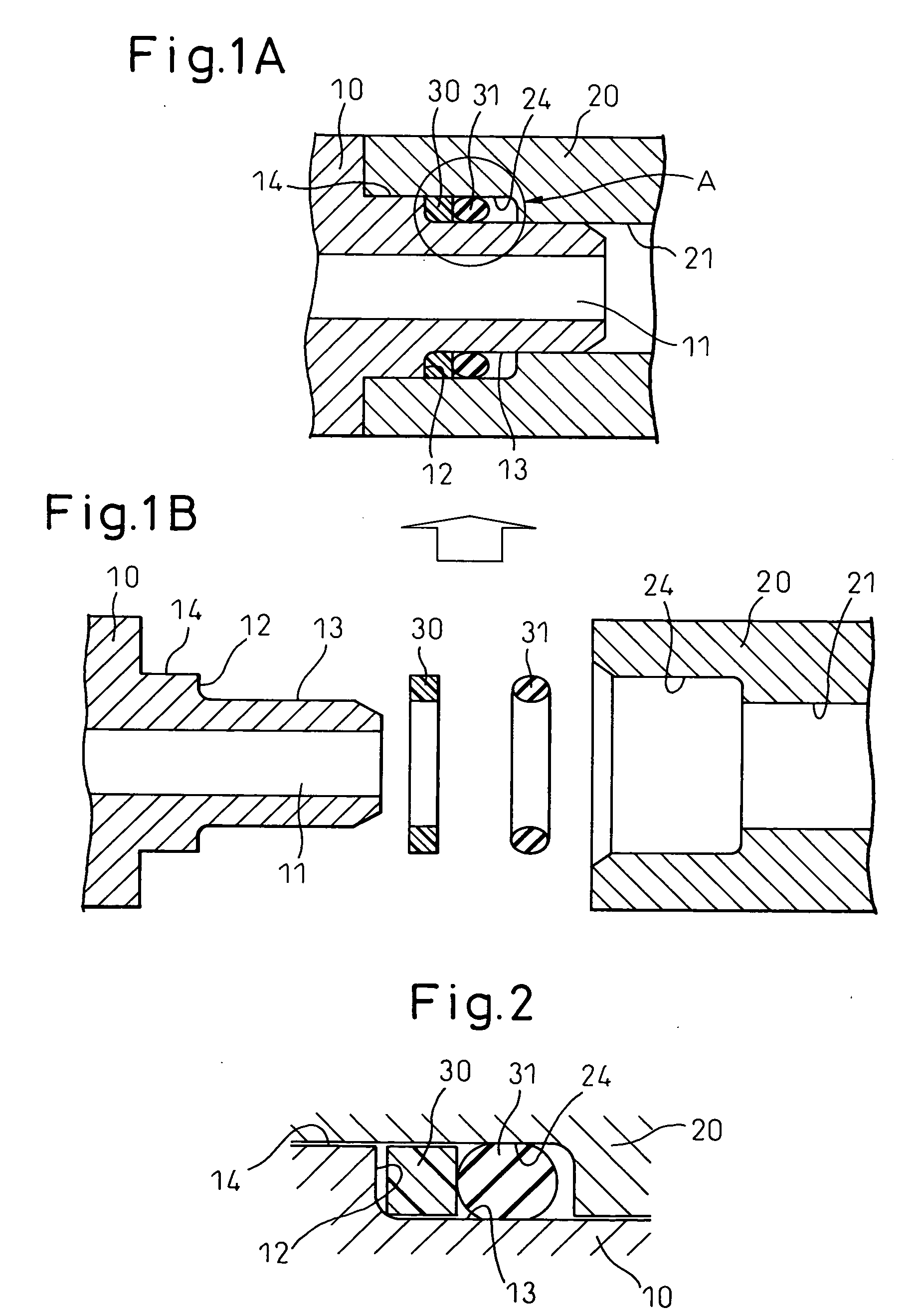
[0020] In the first aspect of the invention, the first hermetic sealing-member (30) arranged in the direction communicating with the atmosphere side is formed of a plastically deformable resin material having a smaller permeability coefficient than the second hermetic sealing-member (31) of an elastic material. Thus, the permeability coefficient to carbon dioxide refrigerant in the supercritical state can be reduced considerably as compared with the conventional material of PTFE (polytetrafluoroethylene). As a result, the amount of the refrigerant leaking through the first hermetic sealing-member (30) and the second hermetic sealing-member (31) can be minimized.
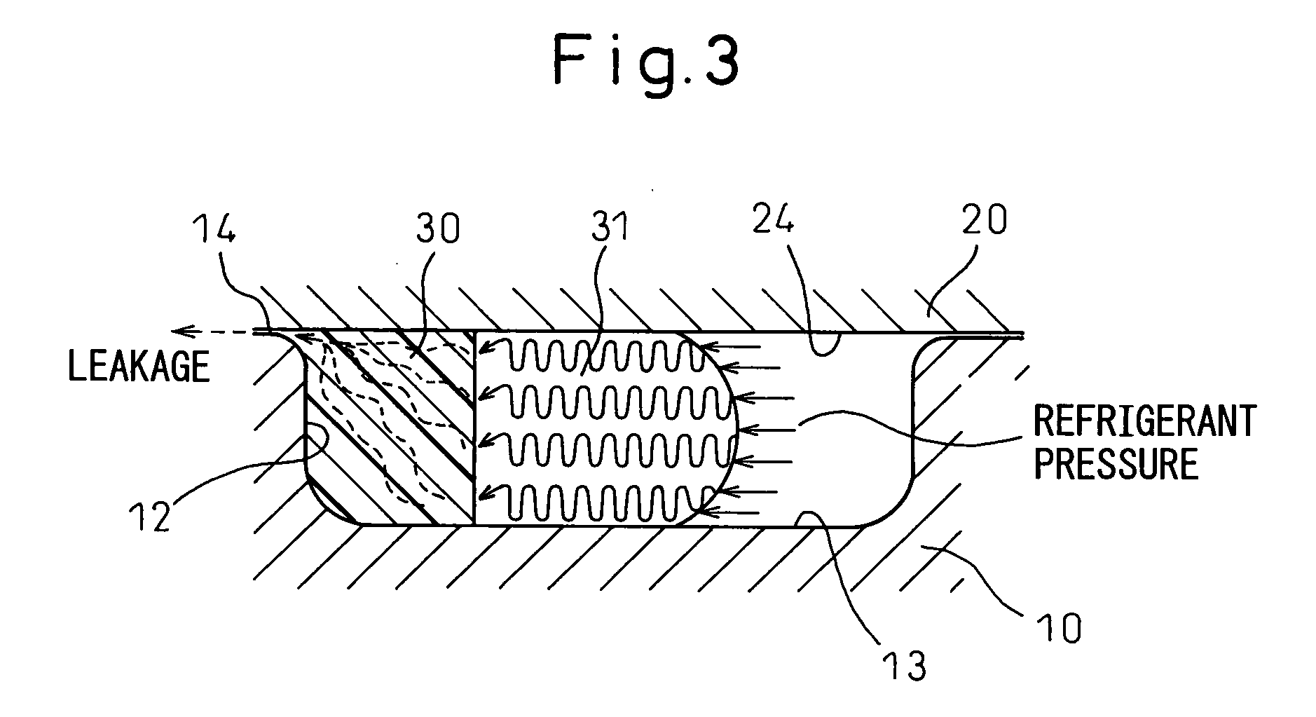
[0021] Further, as the first hermetic sealing-member (30) is formed of a plastically deformable resin material, the gap generated between the fitting recess (24) and the first hermetic sealing-member (30) can be positively filled due to the refrigerant pressure from the second hermetic sealing-member (31) for an improved hermeticity.
[0022] As compared with the conventional bias cut structure, the first hermetic sealing-member (30) is formed as an endless ring without seams, and therefore the refrigerant leakage which otherwise might be caused through the seams can be eliminated.
[0023] As the contact area with the pressure-fitting wall portion (12) is reduced, the stress on the first end surface is increased, thereby improving the hermeticity in the boundary surface with the pressure-fitting wall portion (12).
[0026] According to a fourth aspect of the invention, there is provided a pipe joint for the refrigeration cycle, wherein the first hermetic sealing-member (30) is formed of selected one of PA11 (nylon 11), PA12 (nylon 12) and HDPE (high-density polyethylene). In the fourth aspect of the invention, the second hermetic sealing-member (31) is formed of an elastic material, such as IIR, H-NBR or EPDM, which is high in blister resistance against carbon dioxide refrigerant. Nevertheless, the former materials have a permeability coefficient to carbon dioxide refrigerant, and smaller than the latter materials, and, therefore, the refrigerant leakage due to the permeation can be considerably reduced as compared to a conventional PTFE (polytetrafluoroethylene) material.

Problems solved by technology

Further, as the backup ring 130 is formed by bias cutting, the problem of the refrigerant leaking from the bias cut surface occurs in spite of a high mountability.

Method used


Image

  • Pipe joint for refrigeration cycle having combination of O-ring and backup ring
  • Pipe joint for refrigeration cycle having combination of O-ring and backup ring
  • Pipe joint for refrigeration cycle having combination of O-ring and backup ring

Examples


first embodiment

[0043] (First Embodiment)

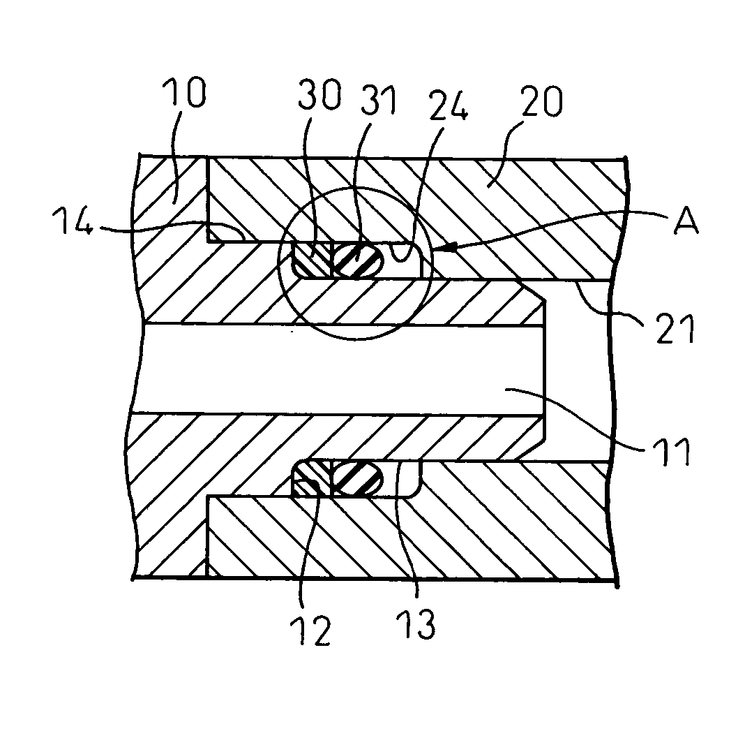
[0044] A pipe joint for the refrigeration cycle according to a first embodiment of the invention is explained below with reference to FIGS. 1 to 5. FIG. 1 shows an example of the application of this invention to a pipe joint by which the refrigerant pipes for the refrigerant cycle using the carbon dioxide refrigerant are connected coaxially.

[0045] This pipe joint, as shown in FIGS. 1A and 1B, comprises a male joint 10 and a female joint 20. The female joint 20 has one end open and the other end connected with refrigerant pipe not shown. A cylindrically shaped refrigerant path 21 and a fitting recess 24 are formed on the inner periphery of the female joint 20.

[0046] The male joint 10 includes a fitting protrusion 14 formed cylindrically at an end thereof, and a stepped portion 13 cylindrically formed and extending toward the forward end from the fitting protrusion 14. The inner periphery of the male joint 10 is formed with a refrigerant path 11, and the oth...

second embodiment

[0064] (Second Embodiment)

[0065] According to the first embodiment described above, the backup ring 30 has a substantially rectangular cross section. Alternatively, instead of the substantially rectangular cross section, the cross section of the backup ring 30 may be substantially polygonal or substantially semicircular as shown in FIG. 6. Specifically, FIG. 6A shows the backup ring 30 with a round form on only one corner of the rectangular section thereof in line with the round form of the pressure-fitting wall portion 12. With this configuration, as in a substantially rectangular form, the backup ring 30 is pressed against the pressure-fitting wall portion 12 and is plastically deformed while being widened along the inner and outer diameters thereof under the refrigerant pressure, thereby filling the gap.

[0066] In FIG. 6B, the backup ring 30 is formed as a substantial polygon with a trapezoidal first end surface thereof in such a manner that the contact area of the first end surf...


PUM

PropertyMeasurementUnit
Temperatureaaaaaaaaaa
Diameteraaaaaaaaaa
Electrical resistanceaaaaaaaaaa

Abstract

A pipe joint for the refrigeration cycle is disclosed. A female joint (20) has a fitting recess (24), and a male join (10) has a fitting protrusion (14) and a stepped portion (13). In the male joint (10) and the female joint (20), a backup ring (30) and an O-ring (31) are fitted adjacently to each other in the stepped portion. The fitting protrusion (14), the backup ring (30) and the O-ring (31) are fitted in a fitting recess (24). The O-ring (31) is formed of an elastic material having a high blister resistance to carbon dioxide refrigerant. The backup ring (30) is formed of a resin material having a smaller permeability coefficient than the O-ring (31) against the carbon dioxide refrigerant and plastically deformable under the pressure of the refrigerant imposed on the O-ring (31). The refrigerant leakage amount can thus be minimized.

Description

BACKGROUND OF THE INVENTION [0001] 1. Field of the Invention [0002] The present invention relates to a pipe joint used to connect refrigerant pipes to each other in a refrigeration cycle or, in particular, to a structure for hermetically connecting an atmospheric side and a refrigerant side through two hermetic sealing-members. [0003] 2. Description of the Related Art [0004] A conventional pipe joint of this type for the refrigeration cycle, which comprises a male joint 100 and a female joint 110 for connecting the refrigerant pipes, as shown in FIG. 7A, is available. [0005] The female joint 110 includes a fitting recess 111 cylindrically formed on the inner periphery thereof. The male joint 100 includes a fitting protrusion 101 formed cylindrically and a stepped portion 102 formed adjacently to the fitting protrusion 101 and having a smaller outer diameter than the fitting protrusion 101. An O-ring 120 constituting a second hermetic sealing-member arranged in the direction communic...

Claims


Application Information

Patent Timeline
IPC IPC(8): F16L17/02B29C65/56B29K23/00B29K77/00B29L23/00F16L21/03F16L21/035F25B41/00
CPCB29C66/71F16L21/03F16L21/035B29C65/00B29K2023/065
Inventor TAKEUCHI, MASAYUKITOMATSU, YOSHITAKASHIOUME, OSAMU
Owner DENSO CORP
Learn More