
Centrifugal-chiller and method for controlling the same

a centrifugal and centrifugal technology, applied in the direction of refrigeration components, machines/engines, lighting and heating apparatus, etc., to achieve the effect of increasing efficiency, high efficiency and high efficiency

Inactive Publication Date: 2012-03-08
MITSUBISHI HEAVY IND LTD
View PDF7 Cites 9 Cited by
  • Summary
  • Abstract
  • Description
  • Claims
  • Application Information

AI Technical Summary

Benefits of technology

[0028]The centrifugal-chiller and the method for controlling the same according to the present invention provide the following operational advantages.
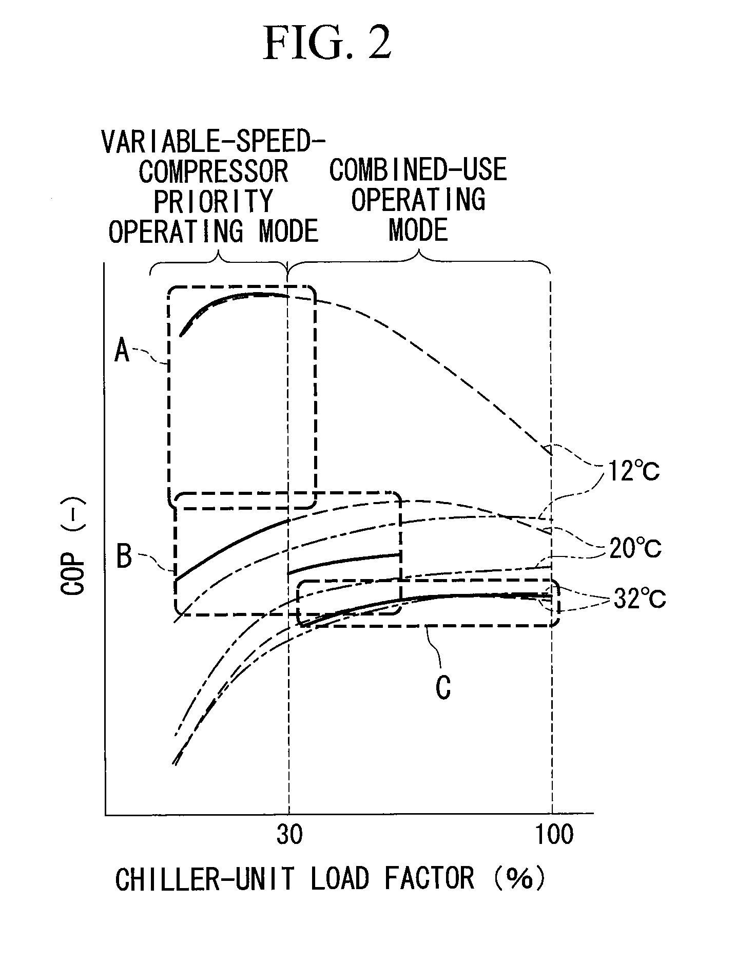
[0029]In the case where the load factor of the centrifugal-chiller is less than a predetermined value, a variable-speed-compressor priority operating mode in which only the variable-speed centrifugal-compressor is activated is selected, and in the case where the load factor of the centrifugal-chiller is the predetermined value or greater, a combined-use operating mode in which the variable-speed centrifugal-compressor and the constant-speed centrifugal-compressor are activated is selected, and thus, a centrifugal-chiller that shows a high COP across wide compressor load factors can be achieved.
[0030]When the cooling water temperature is low as in the winter season during which the cooling water temperature is a predetermined value or less, the variable-speed-compressor priority operating mode is selected, and thus, higher efficiency is achieved.
[0031]When the cooling water temperature is high as in the summer season during which the cooling water temperature is a predetermined value or greater, the combined-use operating mode is selected, and thus, higher efficiency is achieved.
[0032]For the intermediate seasons during which the cooling water temperature is not high as in the summer season and not low as in the winter season, the variable-speed-compressor priority operating mode is selected in the case where the load factor of the centrifugal-chiller is less than a predetermined value, and the combined-use operating mode is selected in the case where the load factor of the centrifugal-chiller is the predetermined value or greater, and a further increased efficiency is achieved.
[0033]A sealing section that minimizes refrigerant leakage is provided between the inlet guide vane and the wall, thereby minimizing refrigerant leakage when the inlet guide vane is fully closed. Thus, even in the variable-speed-compressor priority operating mode, the amount of refrigerant leaked via the constant-speed centrifugal-compressor is minimized, so that deterioration in the performance of the chiller can be prevented.

Problems solved by technology

However, in the case where manufacturing costs can be reduced by using available general-purpose centrifugal-compressors or to cope with high capacity where sufficient performance cannot be achieved by one centrifugal-compressor, two centrifugal-compressors are sometimes provided for one centrifugal-chiller.

Method used


Image

  • Centrifugal-chiller and method for controlling the same
  • Centrifugal-chiller and method for controlling the same
  • Centrifugal-chiller and method for controlling the same

Examples


Embodiment Construction

[0039]An embodiment of the present invention will be described hereinbelow with reference to the drawings.

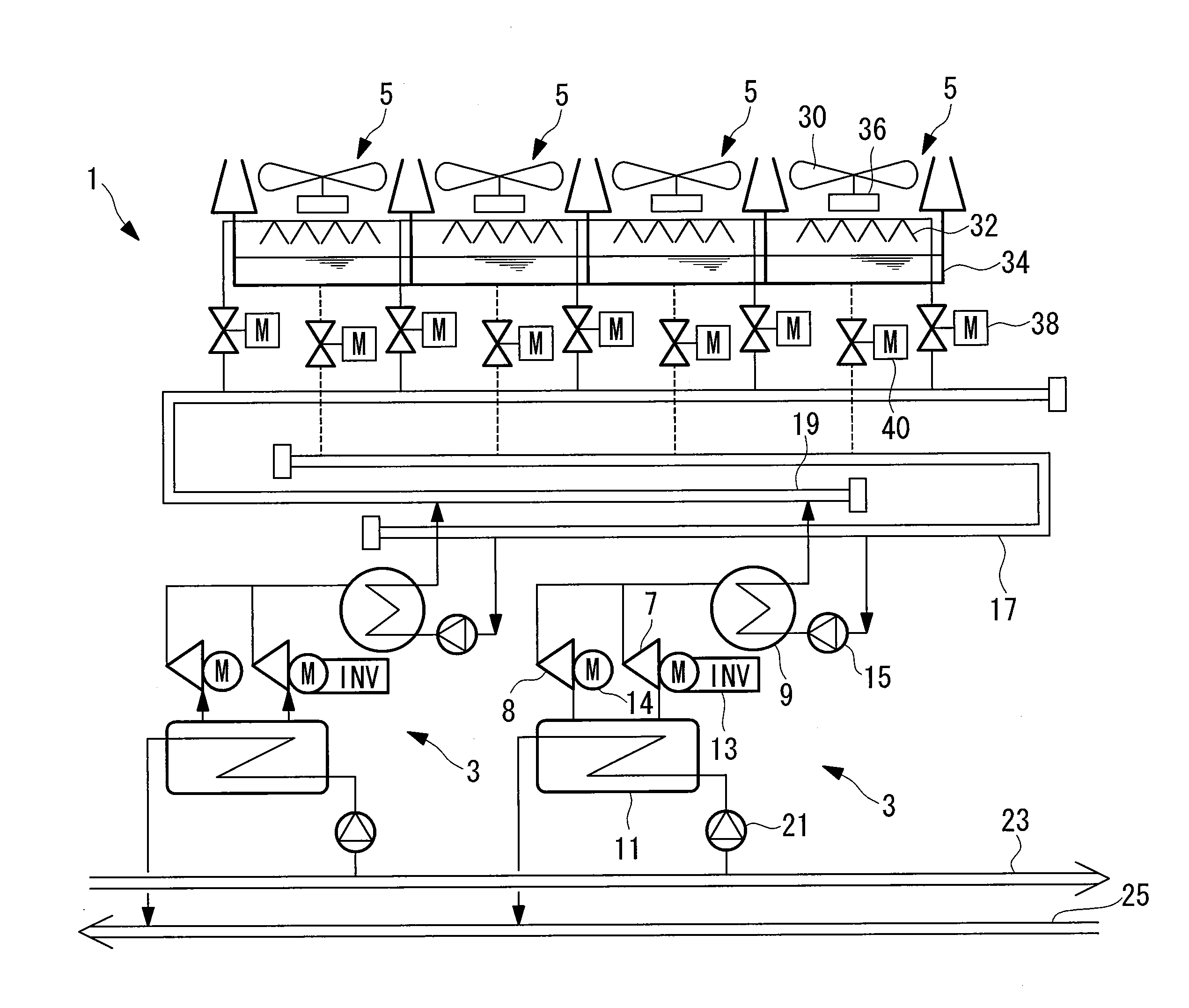
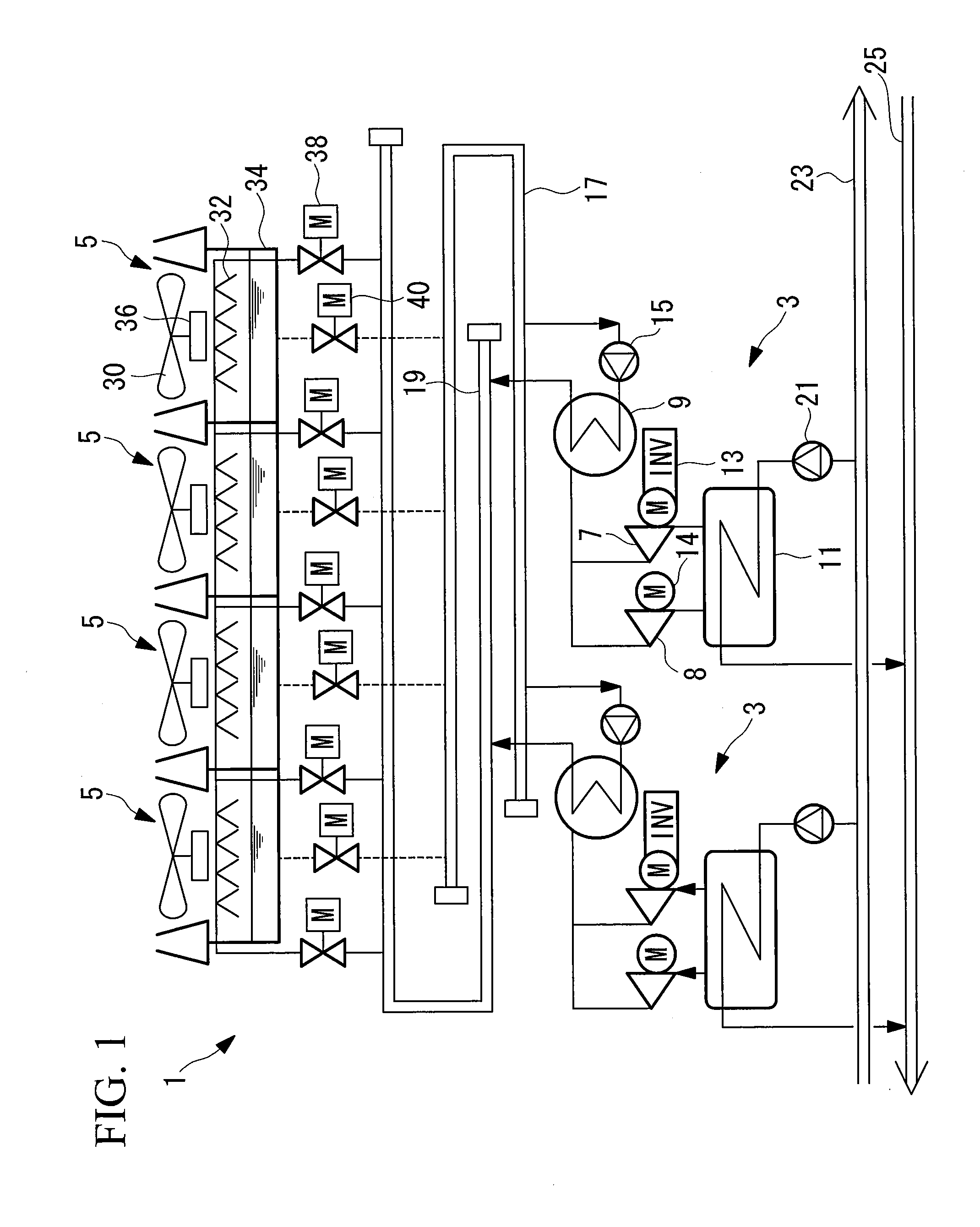
[0040]FIG. 1 shows an embodiment of a heat source system equipped with centrifugal-chillers according to the present invention. A heat source system 1 is equipped with a plurality of (two in this embodiment) centrifugal-chillers 3 provided in parallel and a plurality of (four in this embodiment) cooling towers 5 provided in parallel.

[0041]The centrifugal-chillers 3 are each equipped with two centrifugal-compressors 7 and 8 that compress a refrigerant, a condenser 9 that condenses the refrigerant compressed by the centrifugal-compressors 7 and 8 to liquefy it, an expansion valve (not shown) that expands the refrigerant condensed and liquefied by the condenser 9, and an evaporator 11 that evaporates the refrigerant expanded by the expansion valve.

[0042]One centrifugal-compressor 7 of the two is driven by an electric motor 13 whose rotational frequency can be varied by an inverter....


PUM


Abstract

Provided is a centrifugal-chiller including one variable-speed centrifugal-compressor and one constant-speed centrifugal-compressor and capable of high-efficiency operation. A centrifugal-chiller comprising a variable-speed centrifugal-compressor whose rotational frequency can be varied by an inverter and which compresses a refrigerant; a constant-speed centrifugal-compressor connected in parallel with the variable-speed centrifugal-compressor and operated at a constant rotational speed to compress the refrigerant; and a control unit that controls the operations of the variable-speed centrifugal-compressor and the constant-speed centrifugal-compressor, wherein in the case where a required load factor of the centrifugal-chiller is less than a predetermined value, the control unit selects a variable-speed-compressor priority operating mode in which only the variable-speed centrifugal-compressor is activated, and in the case where the required load factor of the centrifugal-chiller is the predetermined value or greater, the control unit selects a combined-use operating mode in which the variable-speed centrifugal-compressor and the constant-speed centrifugal-compressor are activated.

Description

TECHNICAL FIELD[0001]The present invention relates to a centrifugal-chiller equipped with a variable-speed centrifugal-compressor and a constant-speed centrifugal-compressor and to a method for controlling the same.BACKGROUND ART[0002]Known heat source systems for use in supplying chilled water in semiconductor factories and zoned air conditioning are equipped with centrifugal-chillers. The centrifugal-chillers are equipped with centrifugal-compressors for compressing refrigerant. In general, one centrifugal-compressor is provided for one centrifugal-chiller. However, in the case where manufacturing costs can be reduced by using available general-purpose centrifugal-compressors or to cope with high capacity where sufficient performance cannot be achieved by one centrifugal-compressor, two centrifugal-compressors are sometimes provided for one centrifugal-chiller. In this case, however, centrifugal-compressors having the same capacity are generally disposed in parallel in considerati...

Claims


Application Information

Patent Timeline
Patent Type & Authority Applications(United States)
IPC IPC(8): F25B49/02F25B1/04
CPCF04D25/16F04D27/004F25B1/053F04D27/0269F25B2600/021Y02B30/741F25B2400/075F04D27/0261F25B49/022F25B2400/0751Y02B30/70
Inventor UEDA, KENJI
Owner MITSUBISHI HEAVY IND LTD
Learn More