Expander and expander-compressor unit

a technology of expander compressor and expansion chamber, which is applied in the direction of liquid fuel engines, machines/engines, rotary/oscillating piston pump components, etc. it can solve the problems of refrigerant leakage and lubrication failure, and the layout is difficult to employ, so as to reduce the heat transfer coefficient between fluid and solid, prevent the heat transfer of oil to the expansion mechanism, and reduce the heat transfer of high-temperature oil to the low-temperature expansion mechanism

Inactive Publication Date: 2012-05-15
PANASONIC CORP
View PDF16 Cites 5 Cited by
  • Summary
  • Abstract
  • Description
  • Claims
  • Application Information

AI Technical Summary

Benefits of technology

[0006]An object of the present invention is to provide an expander and an expander-compressor unit capable of improving performance of a refrigeration cycle apparatus by suppressing heat transfer from the oil to the expansion mechanism even when the expansion mechanism is used while being immersed in the oil.
[0017]Generally, the heat transfer coefficient between fluid and solid is increased when the fluid flows faster. Accordingly, the heat transfer from the oil to the expansion mechanism can be prevented by suppressing the oil flow. In the aforementioned expander-compressor unit of the present invention, the oil flow suppressing member suppresses the flow of the oil filling the space between the oil flow suppressing member and the expansion mechanism (the inner reserving space), allowing the heat transfer from the high temperature oil to the low temperature expansion mechanism to be reduced. More specifically, heat flux from the oil to the expansion mechanism is reduced, and heating of the expansion mechanism and also cooling of the compression mechanism by the oil are prevented. Thus, when used for a refrigeration cycle apparatus, the expander-compressor unit of the present invention will demonstrate excellent refrigerating capacity by preventing an increase in enthalpy of the expanded refrigerant. At the same time, it will demonstrate excellent heating capacity by preventing a reduction in enthalpy of the compressed refrigerant. As a result, a refrigeration cycle apparatus with high COP (coefficient of performance) can be realized.

Problems solved by technology

Therefore, it is difficult to employ a layout in which the scroll-type compression mechanism is located at a lower position and the rotary-type expansion mechanism is located at an upper position.
Even if such a layout can be employed, problems of the refrigerant leakage and lubrication failure will arise shortly.

Method used


Image

  • Expander and expander-compressor unit
  • Expander and expander-compressor unit
  • Expander and expander-compressor unit

Examples


second embodiment

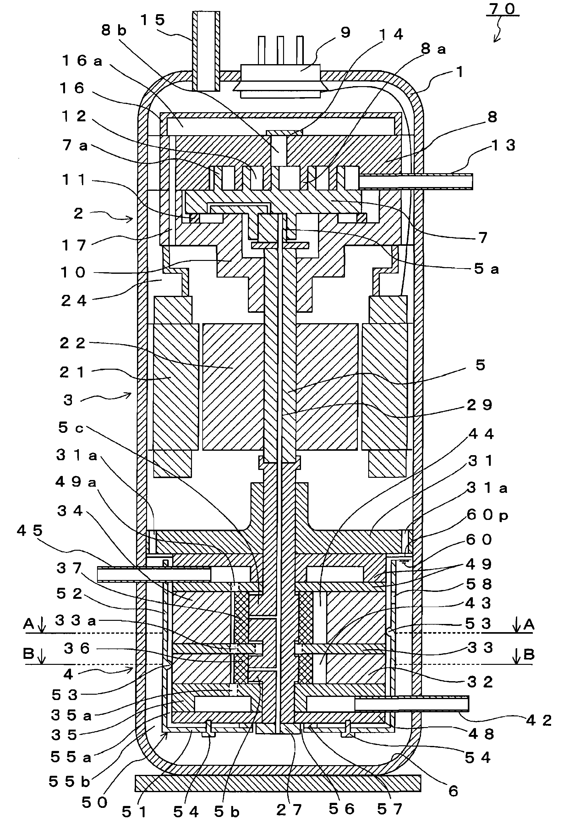
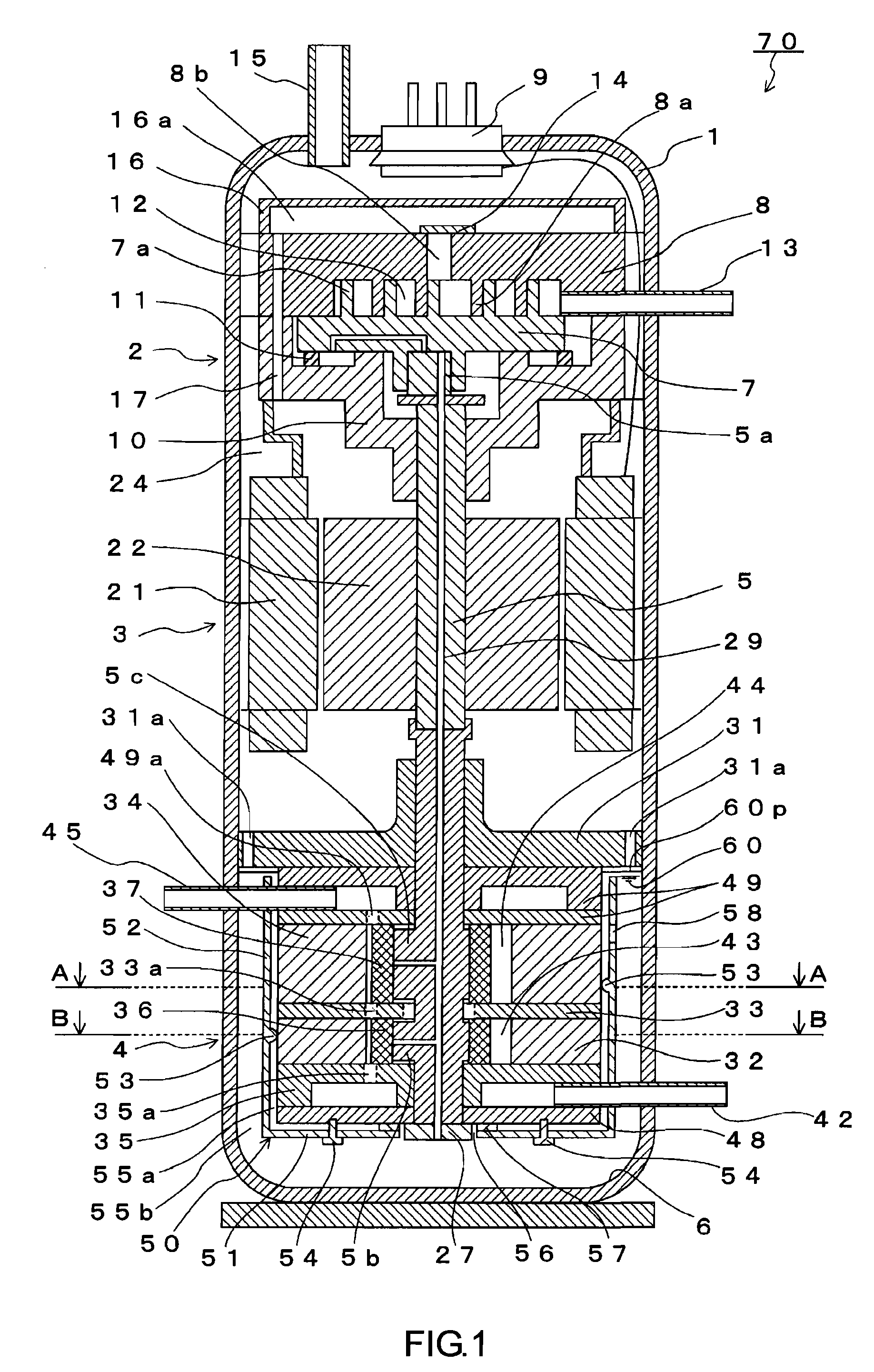
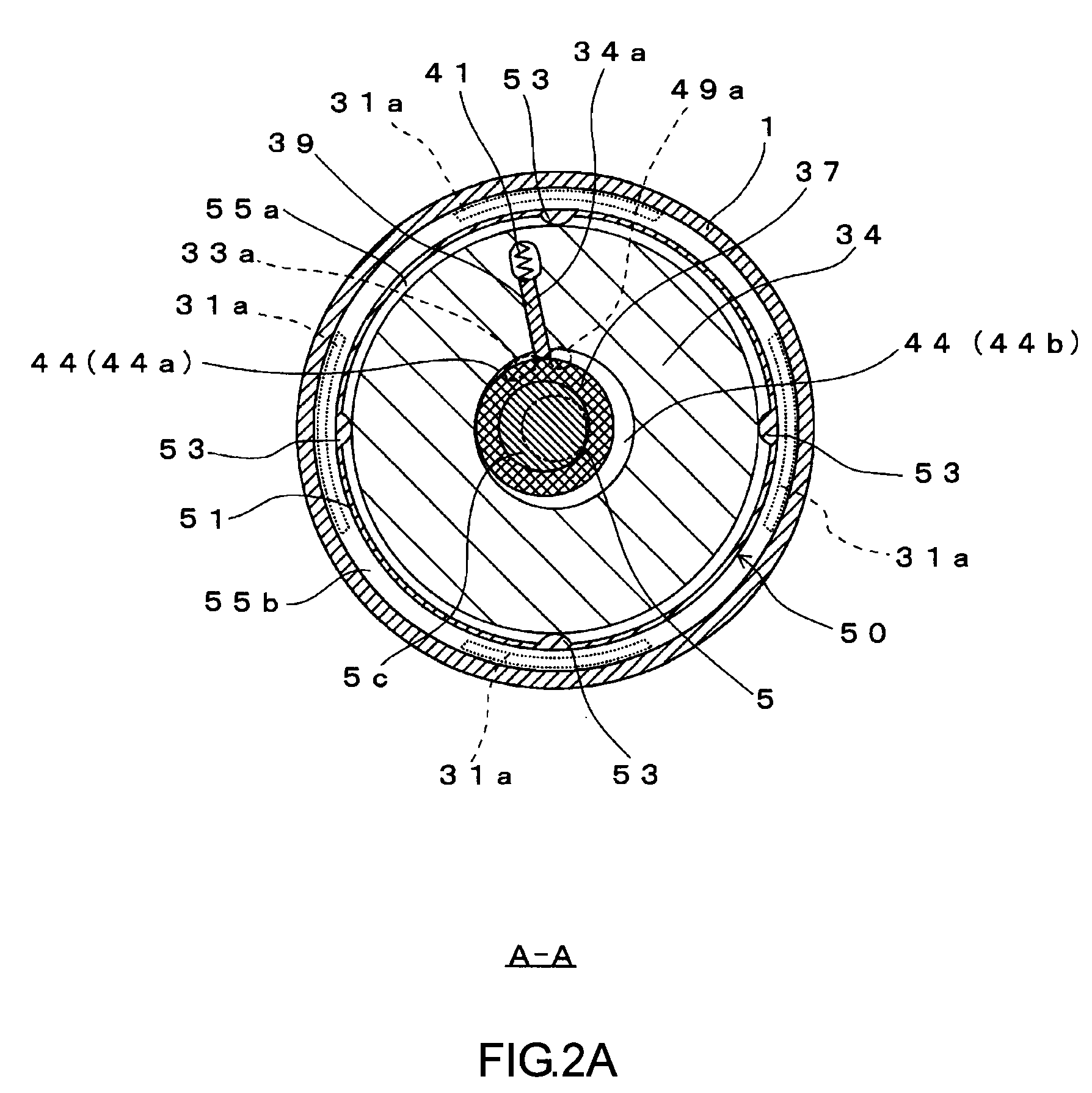
[0071]As mentioned above, the oil flow suppressing member for suppressing the flow of the oil filling the surrounding space of the expansion mechanism 4 does not necessarily have to have a bottom portion. An expander-compressor unit 700 shown in FIG. 6 is provided with an oil flow suppressing member 500 substantially constituted by a tubular portion 520 and spacer portions 53 only. A lower end of the tubular portion 520 is in contact with the bottom portion of the closed casing 1 without any clearance therebetween. In short, the tubular portion 520 is fixed to the bottom portion of the closed casing 1, so the oil 60 cannot flow under the tubular portion 520.

[0072]In the present embodiment, the lower end of the shaft 5 is exposed to the inner reserving space 55a. Thus, an oil supply pipe 61 connecting the oil pump 27 to the outer reserving space 55b is provided so that the oil 60 filling the outer reserving space 55b can be drawn into the oil pump 27 attached to the lower end portion...

third embodiment

[0073]The first embodiment describes an example in which the expander-compressor unit 70 includes the expansion mechanism 4 with the oil flow suppressing member 50 attached thereto. The same configuration also can be employed for an independent expander. An expander 80 of the present embodiment shown in FIG. 7 includes a closed casing 81, an electric generator 30 disposed in the closed casing 81, and the expansion mechanism 4 coupled to the electric generator 30 by a shaft 85. The expansion mechanism 4 is disposed in the closed casing 81 in such a manner that a surrounding space thereof is filled with oil. The oil flow suppressing member 50 is attached to the expansion mechanism 4. The configurations of the expansion mechanism 4 and the oil flow suppressing member 50 are the same as those in the first embodiment. The expansion energy generated during the expansion of the refrigerant is recovered by the expansion mechanism 4, and then is converted into electric power by the electric ...


PUM


Abstract

The expander-compressor unit 70 includes the closed casing 1, the expansion mechanism 4 disposed in the closed casing 1 so that a surrounding space thereof is filled with the oil, the compression mechanism 2 disposed in the closed casing 1 so as to be positioned higher than the oil level, the shaft 5 for coupling the compression mechanism and the expansion mechanism 4 to each other, and the oil flow suppressing member 50 disposed in the surrounding space of the expansion mechanism 4 so that the space 55a filled with the oil is formed between the expansion mechanism 4 and the oil flow suppressing member 50. Thereby the flow of the oil filling the inner reserving space 55a is suppressed, and thus, heat transfer from the high temperature oil to the low temperature expansion mechanism can be reduced.

Description

TECHNICAL FIELD[0001]The present invention relates to an expander for expanding fluid. The present invention also relates to an expander-compressor unit having an integral construction in which a compression mechanism for compressing fluid and an expansion mechanism for expanding fluid are coupled to each other by a shaft.BACKGROUND ART[0002]Apparatuses, so-called refrigeration cycle apparatuses, utilizing a refrigeration cycle of a refrigerant, i.e., compressing, radiating, expanding, and vaporizing, are used for a variety of applications, such as air conditioners and water heaters. As an expander-compressor unit used for such refrigeration cycle apparatuses, there can be mentioned a unit designed for improving efficiency of the refrigeration cycle by coupling, with a shaft, an expansion mechanism that converts the expansion energy generated during the expansion of refrigerant under reduced pressure into mechanical energy and recovers the resulting mechanical energy, and a compress...

Claims


Application Information

Patent Timeline
Patent Type & Authority Patents(United States)
IPC IPC(8): F01C3/00F04C18/00F03C2/00
CPCF01C11/004F01C11/008F01C21/04F04C23/008F01C1/3564F04C18/0215F04C2240/809
Inventor OKAICHI, ATSUOTAKAHASHI, YASUFUMIHASEGAWA, HIROSHIMATSUI, MASARUOGATA, TAKESHIWADA, MASANOBU
Owner PANASONIC CORP
Why Eureka
Try Eureka