This helps you quickly interpret patents by identifying the three key elements:
Problems solved by technology
Method used
Benefits of technology
Benefits of technology
[0064] According to the present invention, by storing heat output from the heat pump by a reversible reaction, a high heat storage density can be realized as compared with the conventional heat storage density of 310 kJ / kg (when the temperature is raised to 75° C.) obtained by the sensible heat of water. Therefore, the heat storage system can be made small in size, and hence a compact regenerative heat pump system having a high installation property can be provided.
[0072] Further, by performing the operation under a reduced pressure lower than the atmospheric pressure, the sensible heat of heat storage material can be utilized as a heating source of the heating means for evaporating the stored liquid or the heat means that performs decomposition of solid compound or heating utilized for the elimination reaction from the adsorbent, to the outside air temperature level. Therefore, a regenerative heat pump system capable of effectively using low-temperature exhaust heat can be provided.
Problems solved by technology
Therefore, there arise problems regarding installation and workability such as installation space, weight of hot water storage tank, and load-carrying capacity of installation portion.
Also, in the conventional regenerative heat pump system, the thermal output from a refrigerant having a temperature lower than the reaction temperature is not utilized effectively, which poses a problem in that it is difficult to secure high COP.
In this case, there arises a problem in that the generated heat of reaction cannot be recovered sufficiently.
Also, there arises a problem in that when heat is taken out by utilizing exothermic reaction, the thermal output cannot be provided in a moment because of the heat capacity of a reactor vessel.
Further, there arises a problem in that power is consumed to supply a reactant at this time, or heat cannot be supplied with high energy efficiency.
Method used
Image
Click on the blue label to locate the original text in one second.
Reading with bidirectional positioning of images and text.
Examples
first embodiment
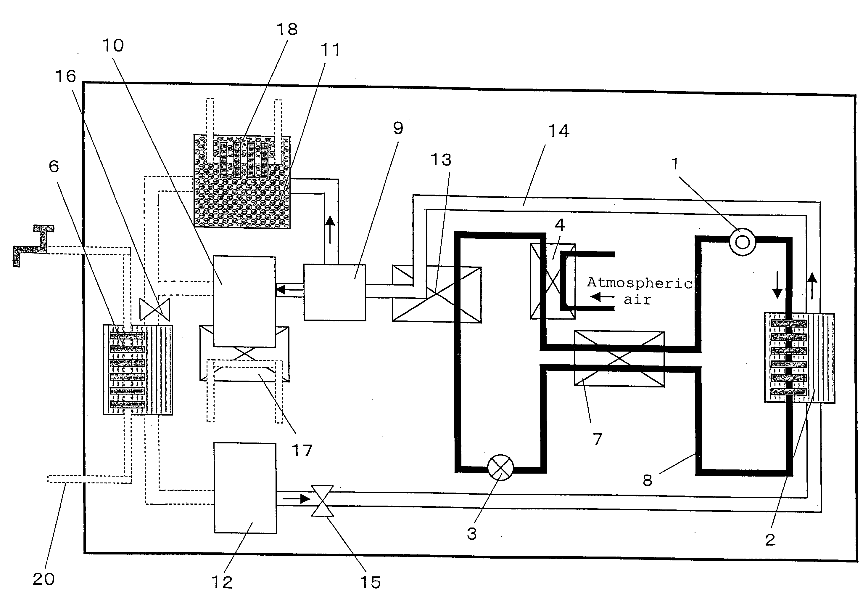
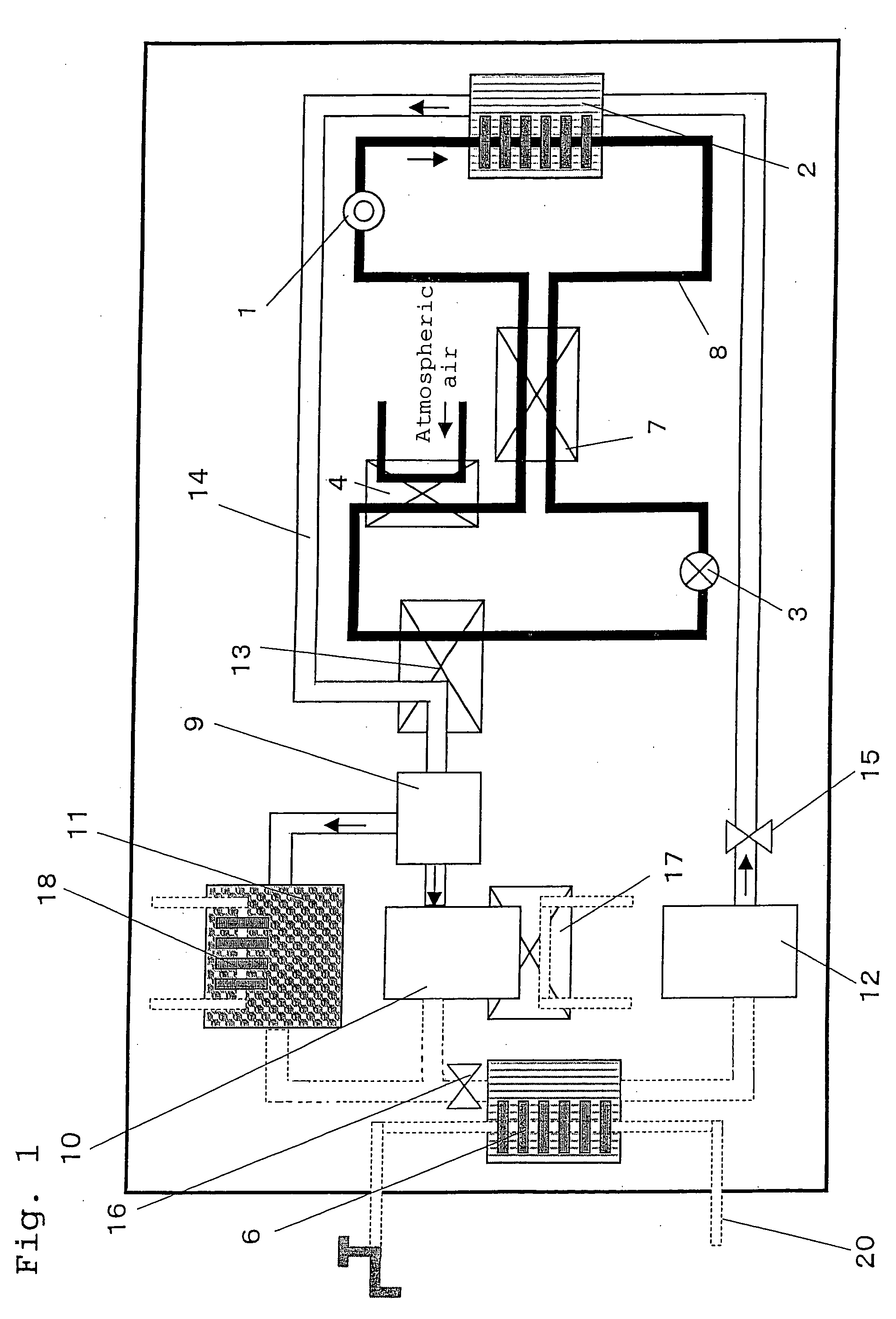
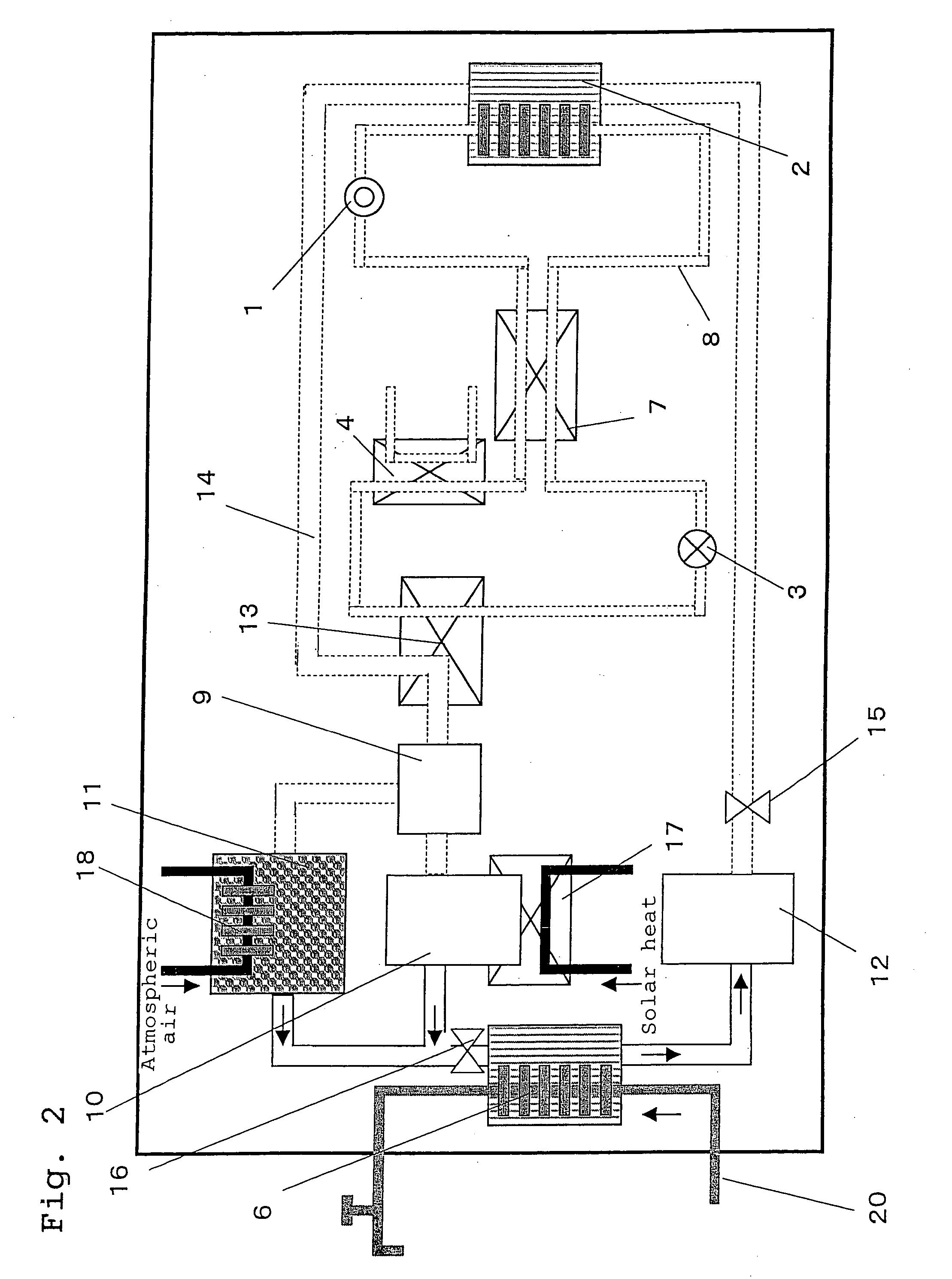
[0117] First, a first embodiment of the present invention will be described.
[0118]FIGS. 1 and 2 are schematic views showing operation states in a heat storage mode and a heat utilization mode, respectively, of a regenerative heat pump system in accordance with a first embodiment of the present invention. A regenerative heat pump system in the first embodiment includes heat generating means 6, a gas-liquid separator 9, an acetone storage vessel 10, a hydrogen storage vessel 11, a 2-propanol storage vessel 12, cooling means 13, a heat storage material flow path 14, a valve A 15, a valve B 16, heating means B 17, heating means C 18, a heating medium flow path 20, and a heat pump cycle. Also, the heat pump cycle is made up of a refrigerant compressor 1, heating means A 2 acting as a refrigerant condenser, a refrigerant expansion valve 3, a refrigerant evaporator 4 that absorbs heat from the atmospheric air to perform an evaporating function, heat recovery means 7, and a refrigerant flo...
second embodiment
[0130] Next, a second embodiment of the present invention will be described.
[0131] The second embodiment is basically the same as the first embodiment except for the reaction system. Specifically, the second embodiment differs from the first embodiment in an integrated configuration of the heating means, heat generating means, and the storage vessel of heat storage material, means of recovering heat from the refrigerant having a temperature lower than the reaction temperature and transferring heat to the refrigerant that is going to flow into the compressor, and a heating source used when the heat storage material in a stored state is supplied. Therefore, hereunder, these points are mainly explained.
[0132]FIGS. 3, 4, 5 and 6 are schematic views showing operation states in a heat storage mode during the heat pump operation, in a heat storage mode after the finish of heat pump operation, and in a heat utilization mode, and a configuration of a detail portion of an adsorbent storage ...
third embodiment
[0157] Next, a third embodiment will be described.
[0158] The third embodiment differs from the second embodiment in a supply source of reaction heat at the time when a heat storage material in a stored state is supplied, and a configuration capable of directly transferring heat from a refrigerant to a heating medium. Therefore, hereunder, these points are mainly explained.
[0159]FIGS. 7, 8, 9 and 10 are schematic views showing operation states in a heat storage mode during the heat pump operation, in a heat utilization mode immediately after the start of heat utilization, in a heat utilization mode, and in a heat utilization mode after the heat storage material in a stored state becomes absent, respectively, of a regenerative heat pump system in accordance with the third embodiment of the present invention.
[0160] A regenerative heat pump system in the third embodiment includes a hydrogen absorbing alloy storage vessel 21, a hydrogen storage vessel 11, a heat storage flow path 14, ...
PUM
Abstract
The present invention provides a regenerative heat pumpsystem including a heat pump cycle, first storage vessel for storing a heat storage material, heat exchange device between first refrigerant and heat storage material for heating and decomposing the heat storage material by heat from a refrigerant, and heat exchange device between second refrigerant and an other heat storage material for transferring heat from the separated heat storage material to the refrigerant. The system also includes second storage vessel for storing the decomposed heat storage material, and heat generating device for generating heat by recombining the heat storage material stored in the second storage vessel and for heating a heating medium. The heat exchange device between the first refrigerant and the heat storage material is also used as a radiator of the heat pump cycle, and the heat exchange device between second refrigerant and the other heat storage material is also used as at least a part of an evaporator of the heat pump cycle.
Description
BACKGROUND OF THE INVENTION [0001] 1. Field of the Invention [0002] The present invention relates to a heat pump system having a small-size heat storage section for storing heat by decomposing or separating a heat storage material by heating. [0003] 2. Related Art of the Invention [0004] A conventional heat pump system having a heat storage section (for example, Japanese Patent Laid-Open No. 11-193958) utilizes a thermal output from a high-temperature and high-pressure refrigerant discharged from a compressor, and stores a large quantity of hot water in a hot water storage tank while repeating a cycle for raising temperature by circulating hot water in the hot water storage tank. [0005] Also, a regenerative heat pump system (for example, Japanese Patent Laid-Open No. 5-288425), which is a combination of a regenerative heat pump and a compression heat pump, utilizes a thermal output from a refrigerant as heat for reaction, and chemically stores heat by storing a substance generated b...
Claims
Application Information
Patent Timeline
Application Date:The date an application was filed.
Publication Date:The date a patent or application was officially published.
First Publication Date:The earliest publication date of a patent with the same application number.
Issue Date:Publication date of the patent grant document.
PCT Entry Date:The Entry date of PCT National Phase.
Estimated Expiry Date:The statutory expiry date of a patent right according to the Patent Law, and it is the longest term of protection that the patent right can achieve without the termination of the patent right due to other reasons(Term extension factor has been taken into account ).
Invalid Date:Actual expiry date is based on effective date or publication date of legal transaction data of invalid patent.

