
Imaging devices and methods

a technology of imaging device and chromatic aberration, applied in the field of refractive optics, can solve the problems of severe chromatic aberration, reduced transmission compared to refractive optics,

Inactive Publication Date: 2005-03-03
INT TECH CENT
View PDF2 Cites 62 Cited by
  • Summary
  • Abstract
  • Description
  • Claims
  • Application Information

AI Technical Summary

Problems solved by technology

The main drawbacks for the FZP are the reduced transmission compared to refractive optics, severe chromatic aberration and th

Method used


Image

  • Imaging devices and methods
  • Imaging devices and methods
  • Imaging devices and methods

Examples


Embodiment Construction

While this invention is susceptible of embodiment in many different forms, there is shown in the drawings and will herein be described in detail specific embodiments, with the understanding that the present disclosure of such embodiments is to be considered as an example of the principles and not intended to limit the invention to the specific embodiments shown and described. In the description below, like reference numerals are often used to describe the same, similar or corresponding parts in the several views of the drawings.

The terms “a” or “an”, as used herein, are defined as one, or more than one. The term “plurality”, as used herein, is defined as two, or more than two. The term “another”, as used herein, is defined as at least a second or more. The terms “including” and / or “having”, as used herein, are defined as comprising (i.e., open language). The term “coupled”, as used herein, is defined as connected, although not necessarily directly, and not necessarily mechanicall...


PUM


Abstract

An imaging device consistent with one of numerous embodiments has an opaque planar sheet with a plurality of pinholes defining a photon sieve in the sheet, wherein, the photon sieve comprises at least first and second regions. The first region exhibits a first focal length, a first field of view, a first transmissivity, a first resolution and a first wavelength, and the second region exhibiting a second focal length, a second field of view, a second transmissivity, a second resolution and a second wavelength. At least one of the first focal length, the first wavelength, the first transmissivity, the first resolution and the first field of view is different from the second focal length, the second wavelength, the second transmissivity, the second resolution and the second field of view. This abstract is not to be considered limiting, since other embodiments may deviate from the features described in this abstract.

Description

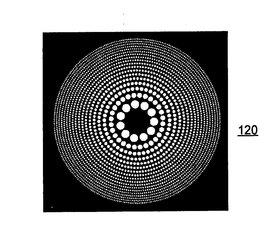
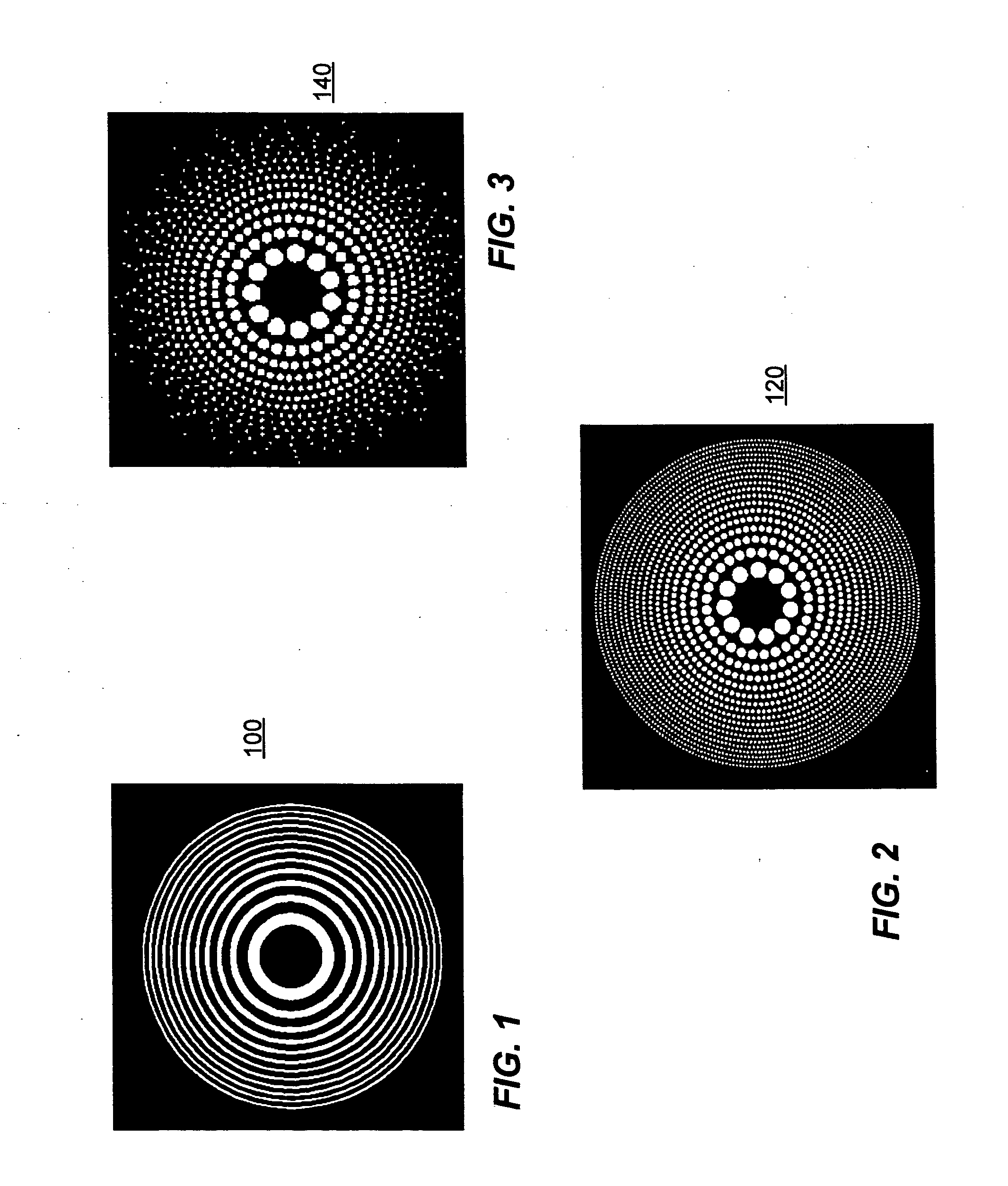
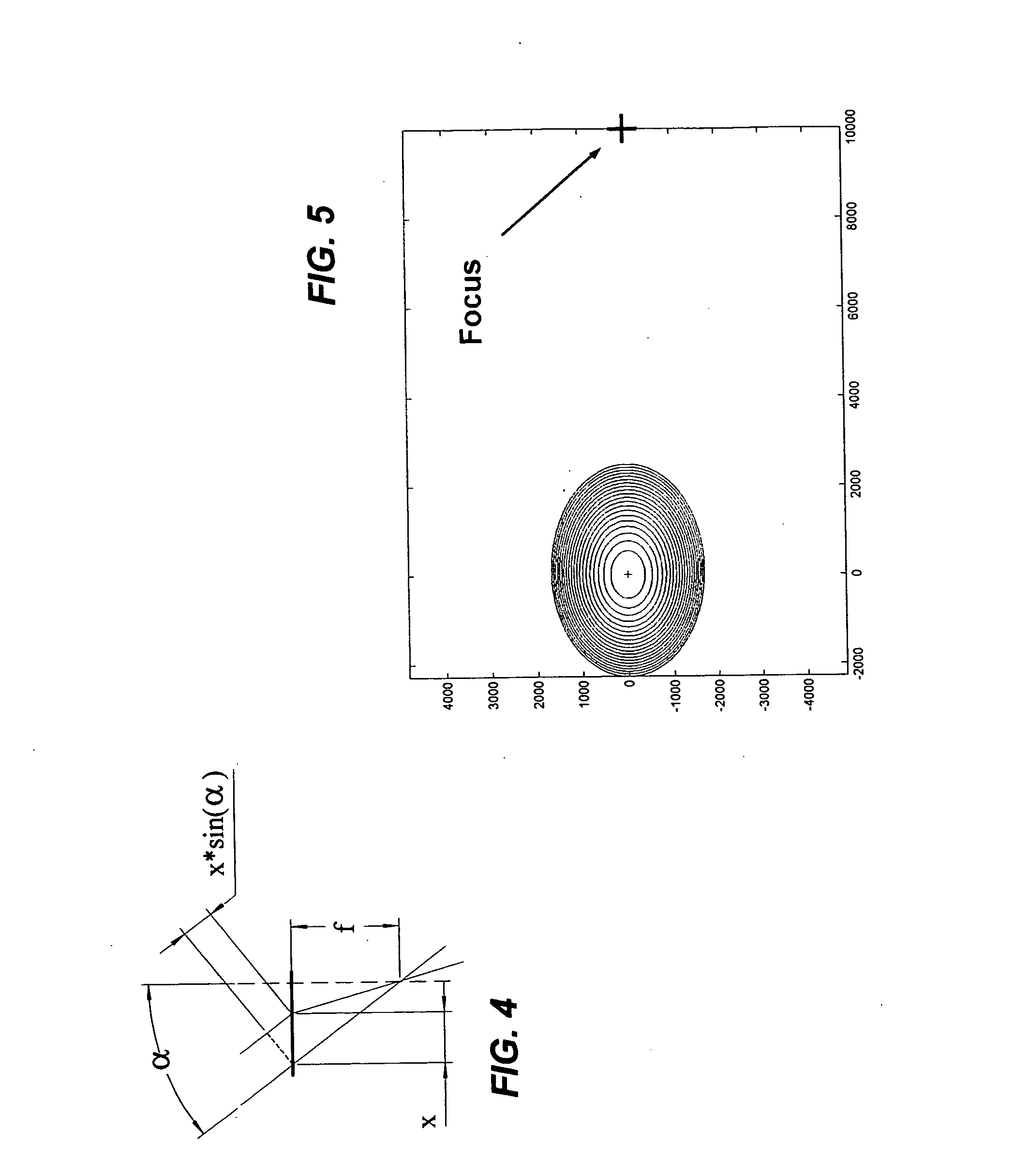
COPYRIGHT NOTICE A portion of the disclosure of this patent document contains material which is subject to copyright protection. The copyright owner has no objection to the facsimile reproduction of the patent document or the patent disclosure, as it appears in the Patent and Trademark Office patent file or records, but otherwise reserves all copyright rights whatsoever. BACKGROUND A Fresnel Zone Plate (FZP), such as FZP 100 shown in FIG. 1, has a set of alternating transmissive and opaque concentric rings that serve as the diffracting elements to focus light. FZPs have been designed to operate at wavelengths that range from the radio wave range to the x-ray range. The ultimate resolution of a FZP is determined by the width of the outermost zone. Fresnel zone plates are attractive alternatives to refractive optics due to savings in size and weight. The main drawbacks for the FZP are the reduced transmission compared to refractive optics, severe chromatic aberration and the presenc...

Claims


Application Information

Patent Timeline
IPC IPC(8): G02B27/44
CPCG02B5/1842G02B27/4205G02B5/188
Inventor SHENDEROVA, OLGA ALEXANDERMCGUIRE, GARY E.SHENDEROV, ALEXANDER DAVID
Owner INT TECH CENT
Learn More