
Mobile communication terminal and wireless communication system

Inactive Publication Date: 2005-03-03
KYOCERA CORP
View PDF18 Cites 67 Cited by
  • Summary
  • Abstract
  • Description
  • Claims
  • Application Information

AI Technical Summary

Benefits of technology

[0030] According to the above-mentioned aspects of the present invention, when the area detection unit of the mobile communication terminal detects that the mobile communication terminal has just entered or left a wireless service area, the notification unit notifies of this event; thus the user can know that he or she has just entered or left a wireless service area of the first communication system which is covered locally. At the same time, a control unit sends to the server positional data of the mobile communication terminal which has been determined by the position determining unit, and the server manages the received positional data as information on the wireless service areas of the first communication system which is covered locally. Thus, it is ensured that the server is always kept updated with latest information on wi

Problems solved by technology

One of the disadvantages of the conventional wireless communication system is time-sensitiveness of hotspot information: the older, the less variable.
However, it is difficult at present for subscribers to obtain hotspot information which was updated one hour ago from sources such as books and televis

Method used


Image

  • Mobile communication terminal and wireless communication system
  • Mobile communication terminal and wireless communication system
  • Mobile communication terminal and wireless communication system

Examples


Example

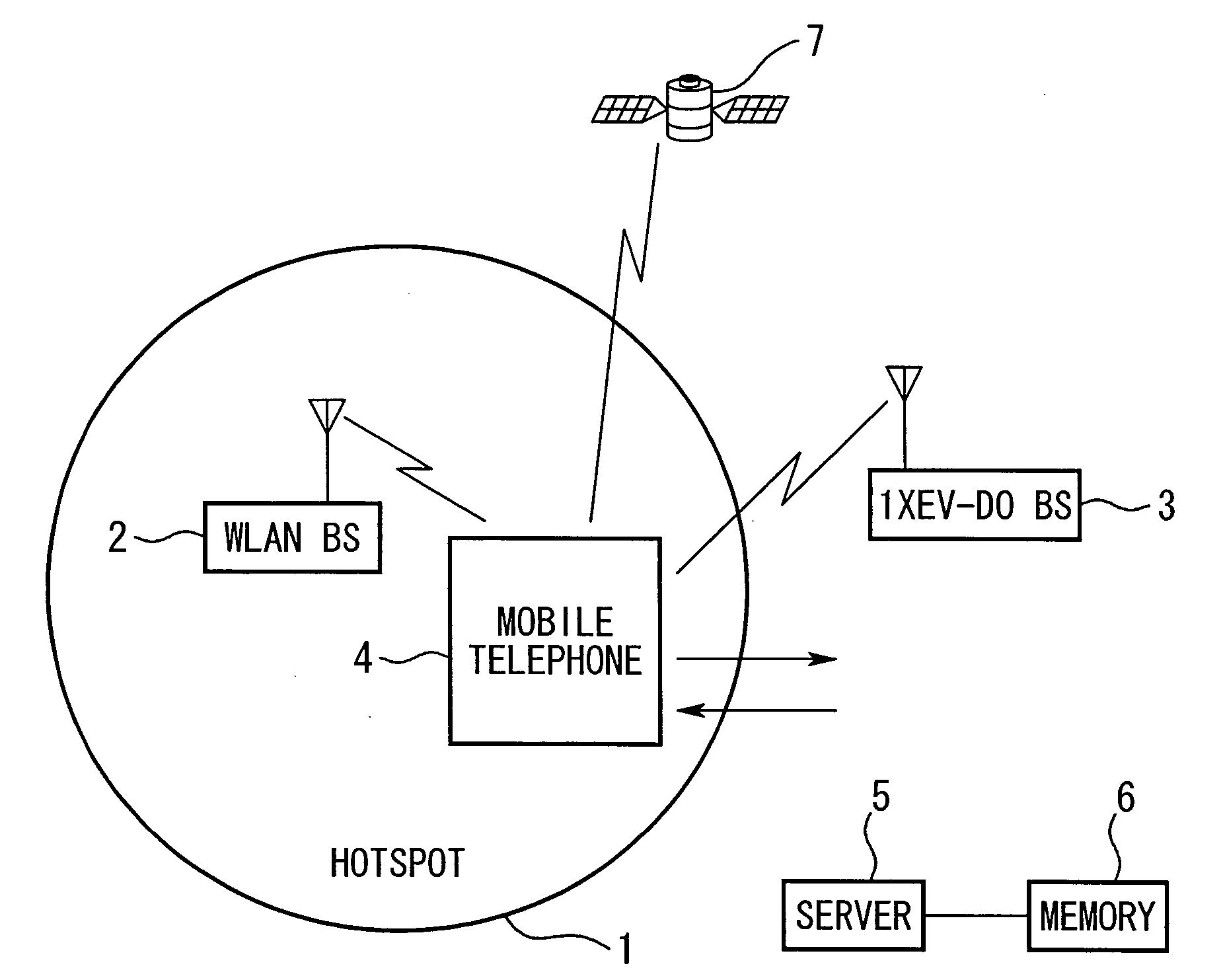
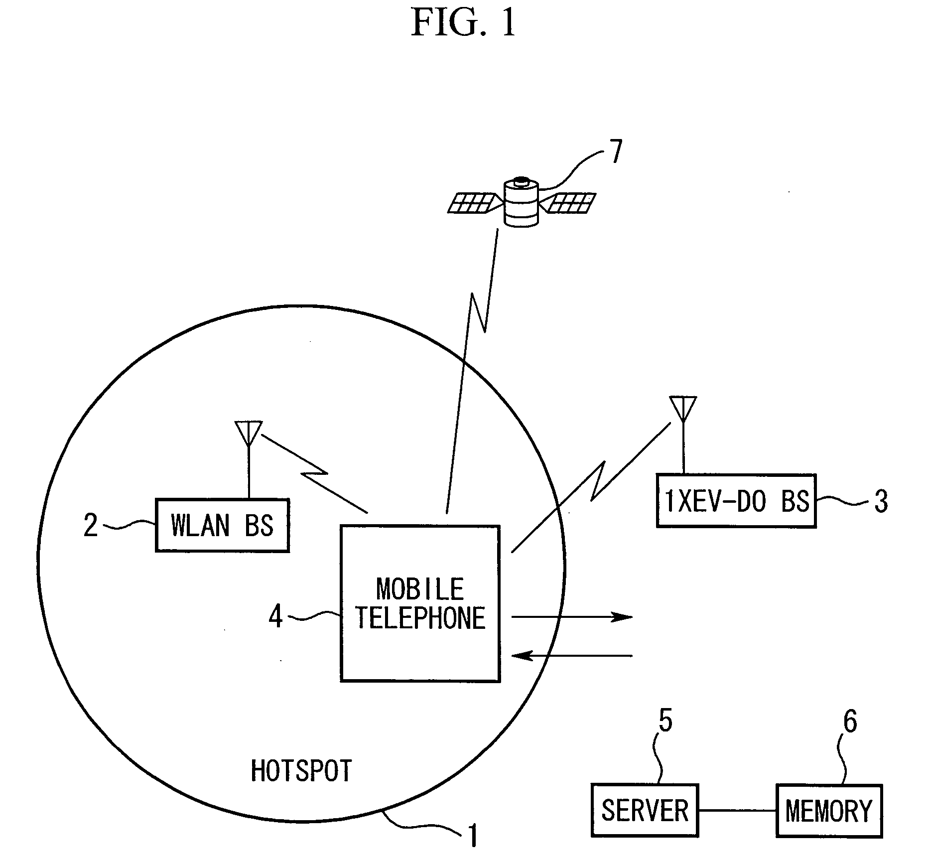
[0035]FIG. 1 illustrates a wireless communication system according to one embodiment of the present invention.

[0036] In a wireless communication system of this embodiment, a mobile telephone is used as dual-mode mobile communication terminal which has two modes of communication: a wireless LAN mode (a first communication mode) for communicating via a first communication system which covers a local area, and another communication mode for communicating via a different communication system, e.g., the CDMA2000 1xEV-DO network (a second communication mode using a second communication system which covers a wide area), and automatically switches between the two modes. For simplicity, the first communication system will be simply refereed to as the “wireless LAN”, and the second communication system will be refereed to as the “CDMA2000 1xEV-DO network” in the following descriptions. Similarly, the first communication mode using the wireless LAN will be simply referred to as the “wireless ...


PUM


Abstract

A mobile wireless communication terminal includes: a first communication unit for communicating over a wireless communication with a first communication system which covers a local area; a second communication unit for communicating over a wireless communication with a second communication system which covers a wide area; an area detection unit for detecting a wireless service area of the first communication system; and a control unit for switching from a second wireless communication path established by the second communication unit to a first wireless communication path established by the first communication unit in response to the area detection unit detecting a wireless service area while communicating over the wireless communication using the second communication unit.

Description

[0001] Priority is claimed on Japanese Patent Application No. 2003-307220, filed Aug. 29, 2003, the content of which is incorporated herein by reference. BACKGROUND OF THE INVENTION [0002] 1. Field of the Invention [0003] The present invention relates to a wireless mobile communication system. More specifically, the present invention relates to a wireless mobile communication terminal which can participate in wireless communication with a communication system which covers a local area, e.g., a wireless local area network (LAN), such as a mobile telephone, and a wireless communication system including such a mobile communication terminal and a server. [0004] 2. Description of Related Art [0005] Recently, high-speed data communication via a wireless LAN using a mobile communication terminal, such as mobile telephones and personal computers, has been offered. For example, a user of a mobile telephone can access to a wireless LAN when the user carrying the mobile telephone is within a “...

Claims


Application Information

Patent Timeline
IPC IPC(8): H04B7/26H04L12/28H04M3/42H04L12/66H04M1/733H04W36/14H04W36/32H04W88/06
CPCH04B7/2628H04W88/06H04W36/32H04W36/14H04W36/0066
Inventor KOJIMA, MASAYA
Owner KYOCERA CORP
Learn More