Optical interconnect system and method of communications over an optical backplane

a backplane and optical interconnection technology, applied in the field of signal communication, can solve the problems of complex timing and conflict resolution systems of optical interconnection devices and methods, and require rather extensive and complex timing and conflict resolution systems of transmitters and receivers

Inactive Publication Date: 2005-03-03
AVAGO TECHNOLOGIED FIBER IP SINGAPORE PTE LTD
View PDF6 Cites 36 Cited by
  • Summary
  • Abstract
  • Description
  • Claims
  • Application Information

AI Technical Summary

Problems solved by technology

However, many of these optical interconnect devices and methods require rather extensive a...

Method used


Image

  • Optical interconnect system and method of communications over an optical backplane
  • Optical interconnect system and method of communications over an optical backplane
  • Optical interconnect system and method of communications over an optical backplane

Examples


Embodiment Construction

[0015] In the following description, reference is made to the accompanying drawing figures which form a part hereof, and which show by way of illustration specific embodiments of the invention. It is to be understood by those of ordinary skill in this technological field that other embodiments may be utilized, and structural, electrical, as well as procedural changes may be made without departing from the scope of the present invention.

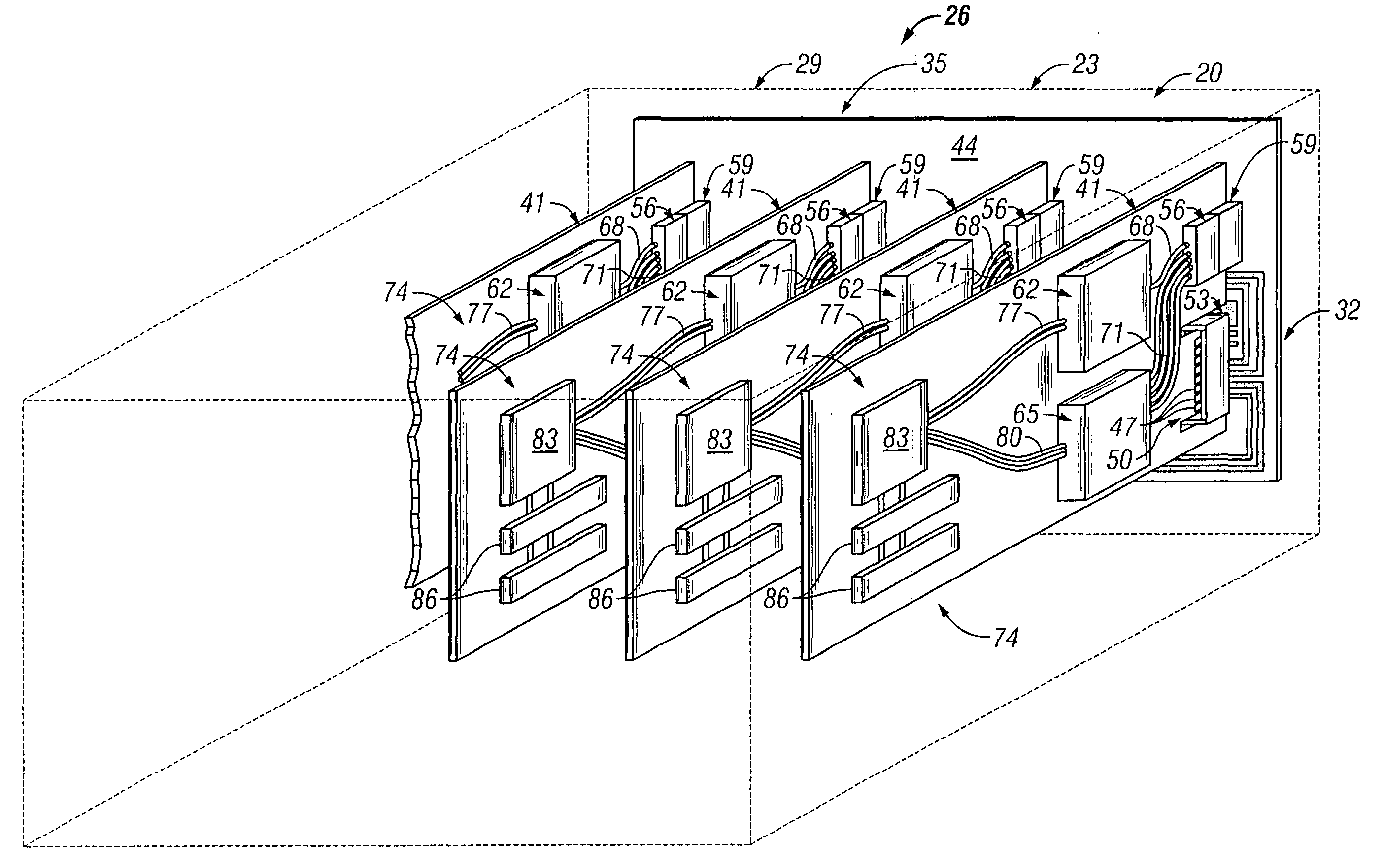
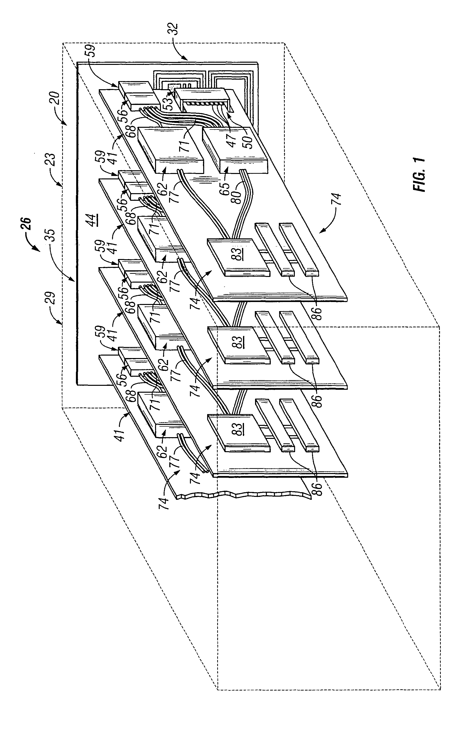
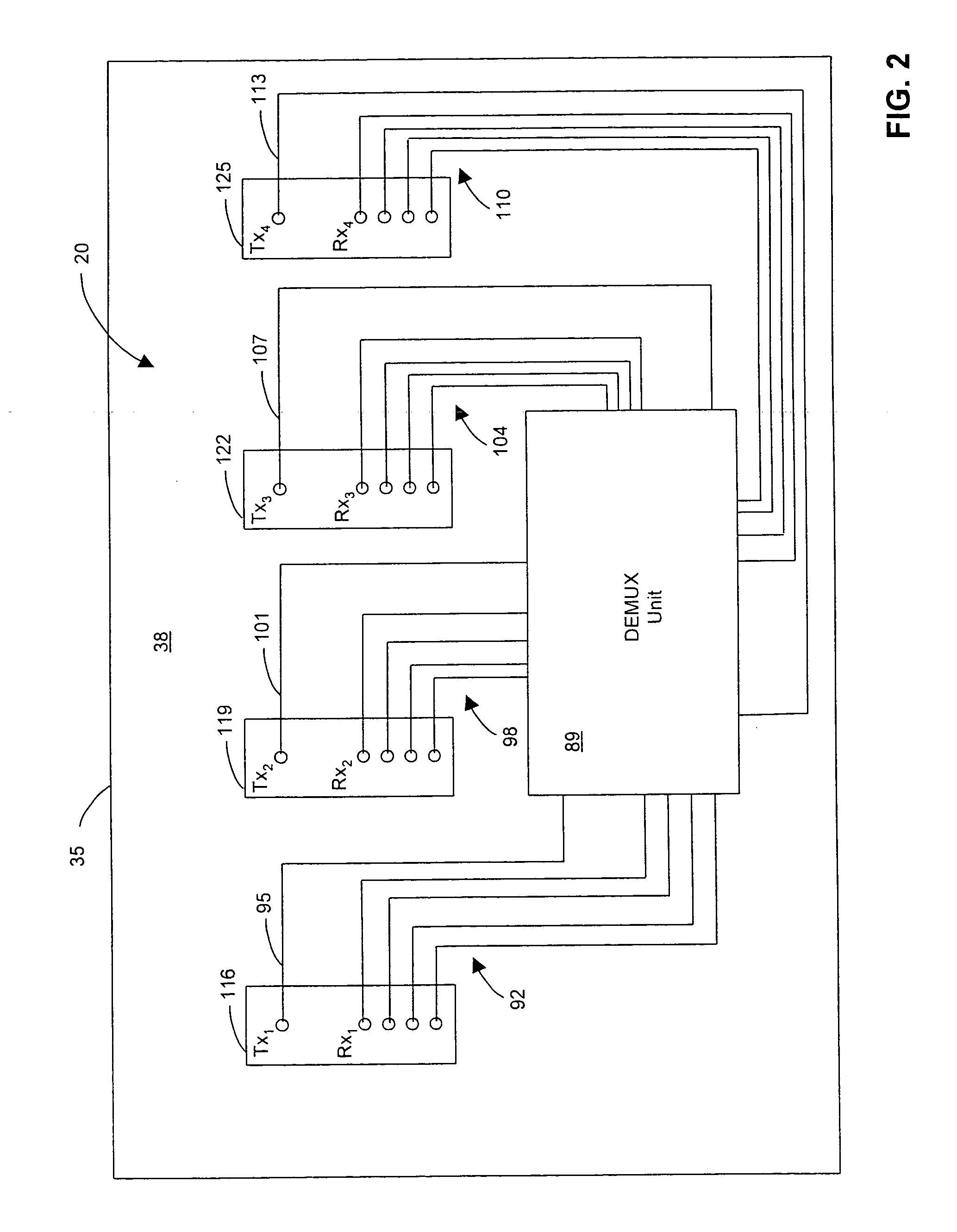
[0016]FIGS. 1 and 2 are perspective and rear views, respectively, of optical backplane 20 configured as a component of electro-optical backplane 23 and electronic device 26. Electronic device 26 may generally include metal casing 29 (shown in dashed lines) housing electrical backplane 32 and connected electrical circuit board 35. Optical backplane 20 is coupled to rear surface 38 of circuit board 35, and a plurality of electro-optical circuit boards 41 are mounted to front surface 44 of circuit board 35. Circuit boards 41 may be disposed in a paralle...


PUM


Abstract

An optical interconnect system includes a plurality of optical circuit boards coupled to an optical backplane. An optical transmitter may be implemented with some or all of the plurality of optical circuit boards. Each optical transmitter is configured to transmit a multi-wavelength light signal. Each of a plurality of optical receivers are separately associated with the plurality of optical circuit boards. In accordance with one embodiment, one or more demultiplexing devices may be used to demultiplex multi-wavelength light signals to discrete wavelengths.

Description

BACKGROUND OF THE INVENTION [0001] 1. Field of the Invention [0002] The present invention relates to signal communications between the integrated circuits of separate electronic modules such as circuit boards, and more particularly to optical signal communications over an optical backplane which uses parallel optics or multi-wavelength optical communications, or both. [0003] 2. Discussion of the Related Art [0004] High speed electrical systems route many high speed electrical signals to multiple destinations having one or more integrated circuits (ICs) or processors which process the signals. Such destinations include the nodes of communication systems, circuit modules, circuit boards, and other such electronic systems or sub-systems. The electrical signals may be transmitted over an electrical backplane that allows the electrical signals to be broadcast to some or all possible destination circuit boards. A destination circuit board merely taps into the electrical backplane through ...

Claims


Application Information

Patent Timeline
IPC IPC(8): G02B6/42G02B6/28G02B6/34G02B6/43H04B10/00H04B10/12H04B10/135H04B10/14H04B10/2581H04J14/00H04J14/02
CPCG02B6/2804H04J14/02H04B10/801G02B6/43
Inventor WINDOVER, LISA A.SIMON, JONATHAN
Owner AVAGO TECHNOLOGIED FIBER IP SINGAPORE PTE LTD
Why Eureka
Try Eureka