Apparatus and method for joining tubulars

a tubular member and joint restraint technology, applied in the direction of packaging, manufacturing tools, couplings, etc., can solve the problems of inability to adapt to the material or geometry of tubular members, and other joint restraint arrangements are not readily adaptable to accommodate variations in tubular member material or geometry, so as to improve joint restraint reliability and stable clamping force

Inactive Publication Date: 2005-03-03
STAR PIPE PRODS
View PDF23 Cites 8 Cited by
  • Summary
  • Abstract
  • Description
  • Claims
  • Application Information

AI Technical Summary

Benefits of technology

[0008] The present invention provides a robust joint restraint that incorporates features and arrangements that enhance joint restraint reliability and produce a stable clamping force for joining tubular members. The invention may be advantageously applied to a restraint that has a gland that fits around a tubular member, a plurality of pads adapted to apply a clamping force on the tubular member, and a plurality of bolts that move the pads from a retracted position to an extended position.
[0009] In a first aspect, the present invention provides selective and controlled relative movement between the pad and the gland of the joint restraint. The relative movement between the pad and the gland is controlled by use of a dampening force. This dampening force can be generated by a mechanical device, a chemical, or by known natural forces such as a magnetic field. In a preferred embodiment, a flexible member associated with the pad applies a compressive force against an interior surface of the gland. This flexible member dampens relative movement between the pad and the gland. Further, the flexible member can extend into and be captured by a recess formed into the interior surface. The material and configuration of the flexible member can be adjusted to provide a selective amount of dampening force.
[0011] In a third aspect, the present invention provides an articulated wedging interface between the pad and the bolt. This wedging interface includes a frustoconical section formed on a tip of the bolt and a generally planar surface on the pad. Relative movement between the tubular member and the pad causes the pad to wedge against the bolt tip in a controlled fashion. This action can cause supplemental penetration of the teeth into the surface of the tubular member and / or generate an enhanced clamping force.
[0012] In a fourth aspect, the present invention provides a tooth arrangement that enhances the clamping action of the pad. A preferred arrangement includes a plurality of teeth that are offset from the edges of the pad with a landing. Additionally, a predetermined amount of spacing is provided between the teeth in order to produce a discontinuous or intermittent penetration or incision pattern on the outer surface of the tubular member. This incision pattern reduces the risk that the incisions will affect the structural integrity of the tubular member. Preferably, at least two teeth are substantially aligned along a first circumference. In a related embodiment, a third tooth is substantially aligned on a second circumference that is different from said first circumference to form a tripod arrangement.

Problems solved by technology

Once the pad is extended, however, the frangible material is disturbed in such a way that it can no longer effectively retain the pad.
Still other joint restraint arrangements are not readily adapted to accommodate variations in tubular member material or geometry.

Method used


Image

  • Apparatus and method for joining tubulars
  • Apparatus and method for joining tubulars
  • Apparatus and method for joining tubulars

Examples


Embodiment Construction

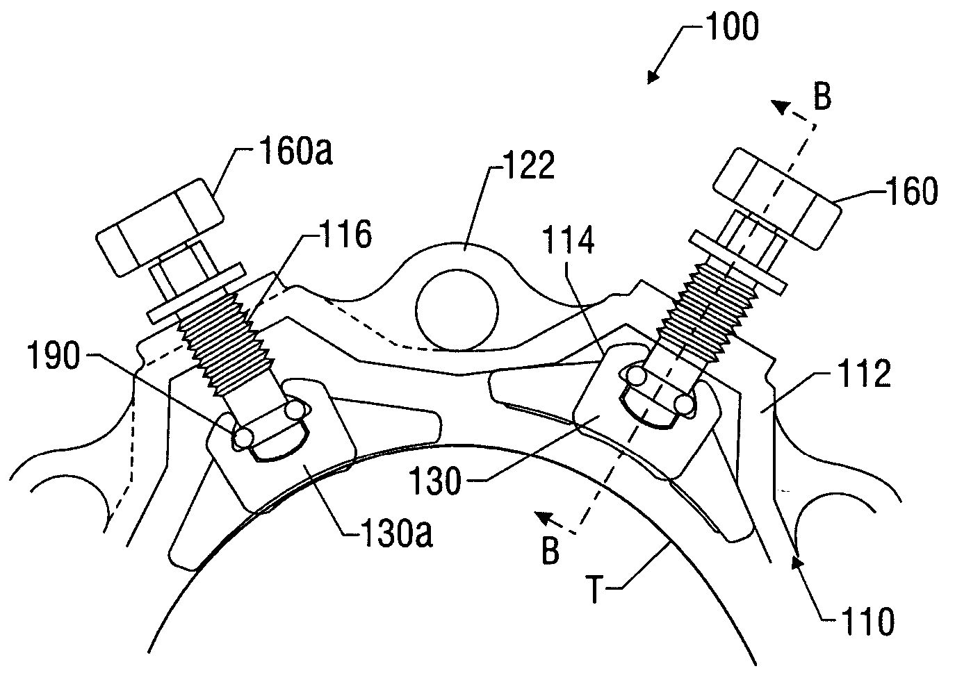
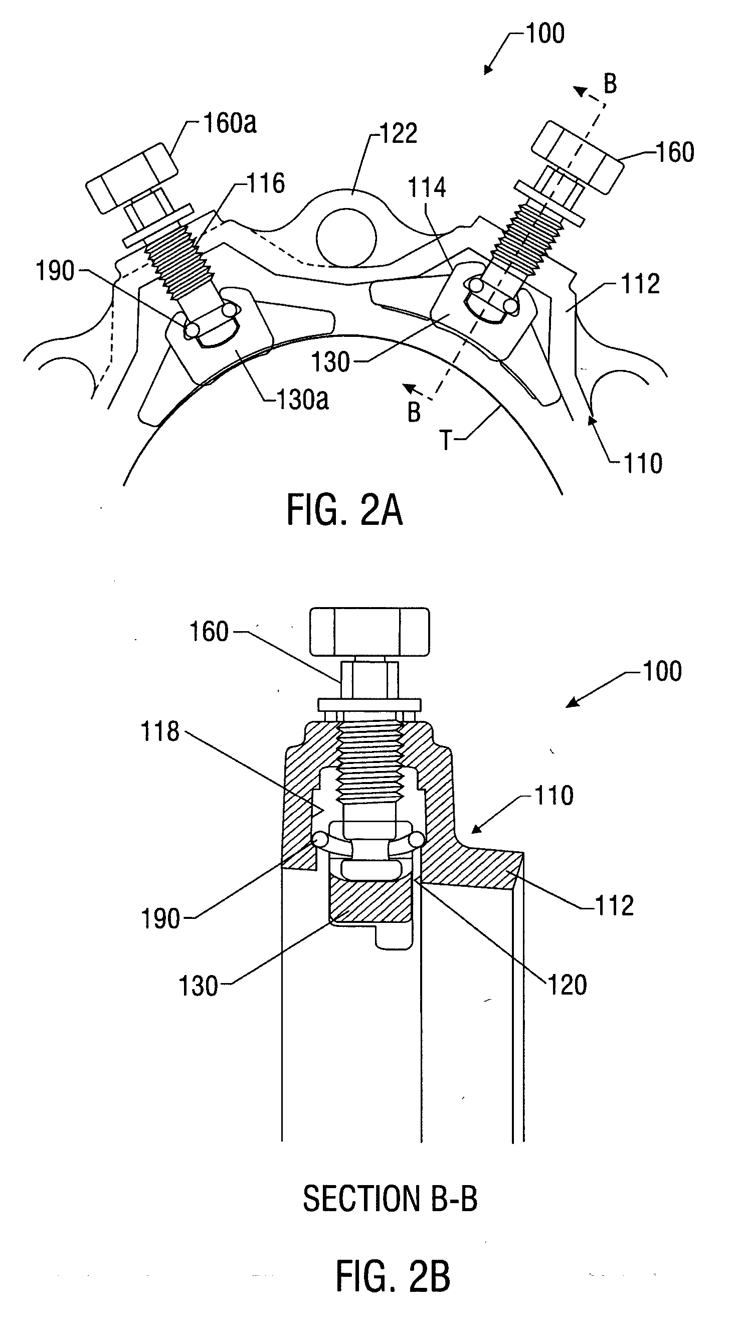
[0033] The present invention relates to devices and methods providing rugged and cost-effective joint restraint that provides an enhanced clamping force for joining tubular members. The present invention is susceptible to embodiments of different forms. There are shown in the drawings, and herein will be described in detail, specific embodiments of the present invention with the understanding that the present disclosure is to be considered an exemplification of the principles of the invention, and is not intended to limit the invention to that illustrated and described herein.

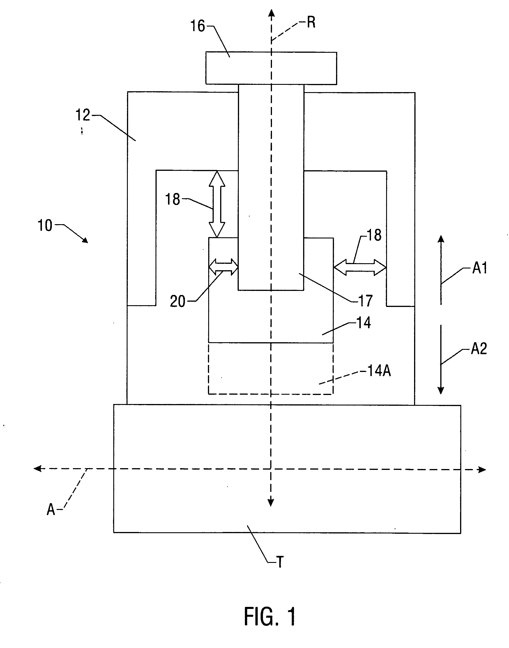
[0034] Referring initially to FIG. 1, there is schematically illustrated an exemplary coupling 10 made in accordance with the present invention. The coupling 10 is shown positioned about an end of a tubular member T. In the following description of the advantageous features of the coupling 10, the term “radial” movement denotes movement along axis R and “axial” movement denotes movement along axis A. Further, ...


PUM


Abstract

A preferred joint restraint includes a dampening force and a restraining force to control relative movement between a pad and gland and between the gland and bolt, respectively. The preferred restraint includes a gland, pads, and bolts. Preferably, a flexible member disposed in the pad selectively provides the dampening and retaining force. A preferred joint restraint also includes a pad and a bolt that coact to provide a controlled wedging action. The wedging action supplies supplemental tooth penetration and / or enhanced clamping force that stabilizes a shifting tubular member (pipe). A preferred tooth arrangement for a restraint pad produces an intermittent penetration pattern in the pipe. A preferred spacing member for a restraint tunes a clamping force generated by the restraint to accommodate variations in pipe geometry and / or materials. A preferred restraint is arranged according to a method that uses pipe expansion to provide an enhanced gripping action.

Description

CROSS-REFERENCE TO RELATED APPLICATIONS [0001] None. BACKGROUND OF THE INVENTION [0002] 1. Field of the Invention [0003] The present invention relates to joint restraints for tubular members. More particularly, the present invention relates to systems and methods for controlling the relative movement of components making up a joint restraint and controlling the clamping force applied to tubular members. [0004] 2. Description of the Related Art [0005] Joint restraints are typically used to couple two axially-aligned tubular members such as pipes. A conventional joint restraint includes an annular body or gland fitted with a plurality of evenly spaced pads or wedges. Each pad has an associated bolt that, when rotated, urges the pad radially inward from a retracted position to an extended position. During extension, the teeth projecting out of the pad contact an outer surface of a first tubular member. The gland becomes substantially fixed onto the first tubular member as bolt rotation...

Claims


Application Information

Patent Timeline
Patent Type & Authority Applications(United States)
IPC IPC(8): F16L25/06
CPCF16L25/065Y10T403/5741Y10T403/7062
Inventor WALWORTH, VAN T.HOOK, DAVID B.BOWSHER, MARKJAIN, ASHISH
Owner STAR PIPE PRODS
Why Eureka
Try Eureka