Prosthetic hip joint with side pivot

a hip joint and side pivot technology, applied in the field of prosthetic hips, can solve the problems of unnatural load applied to the torso of amputees, difficult to construct a cosmesis that can effectively maintain the desired cosmetic effect, and sizable moment at the join

Inactive Publication Date: 2005-03-03
WILSON MICHAEL T
View PDF14 Cites 31 Cited by
  • Summary
  • Abstract
  • Description
  • Claims
  • Application Information

AI Technical Summary

Benefits of technology

[0006] The present invention comprises a prosthetic hip having a side pivot point and a vertically aligned load point that is offset from the pivot point. The present prosthetic hi

Problems solved by technology

For example, because the hip joint itself is not aligned with the natural weight-bearing line of the amputee's body, an unnatural load is applied to the torso of the amputee and a sizable moment occurs at t

Method used


Image

  • Prosthetic hip joint with side pivot
  • Prosthetic hip joint with side pivot
  • Prosthetic hip joint with side pivot

Examples


Embodiment Construction

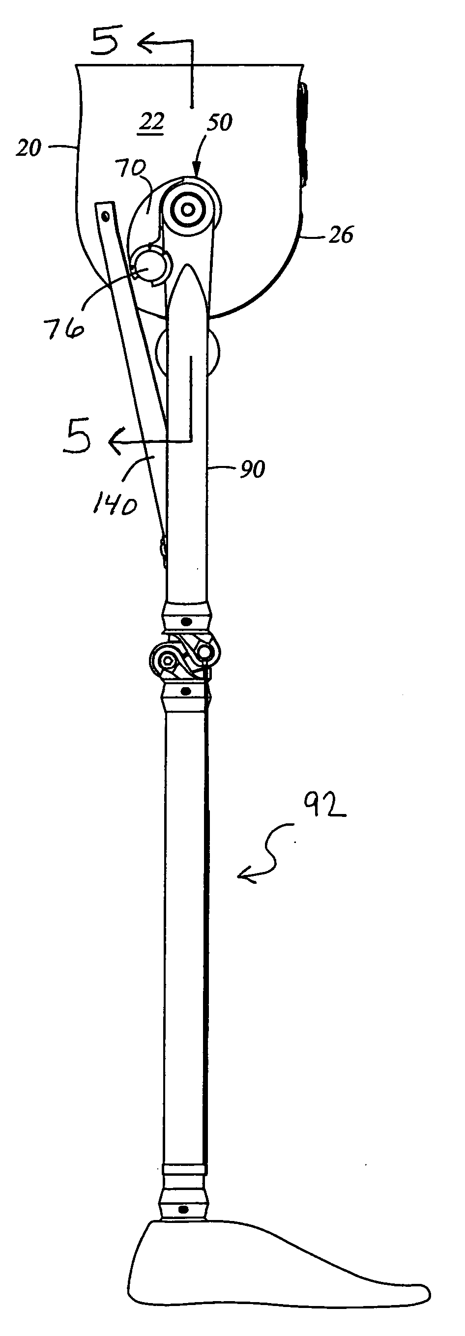
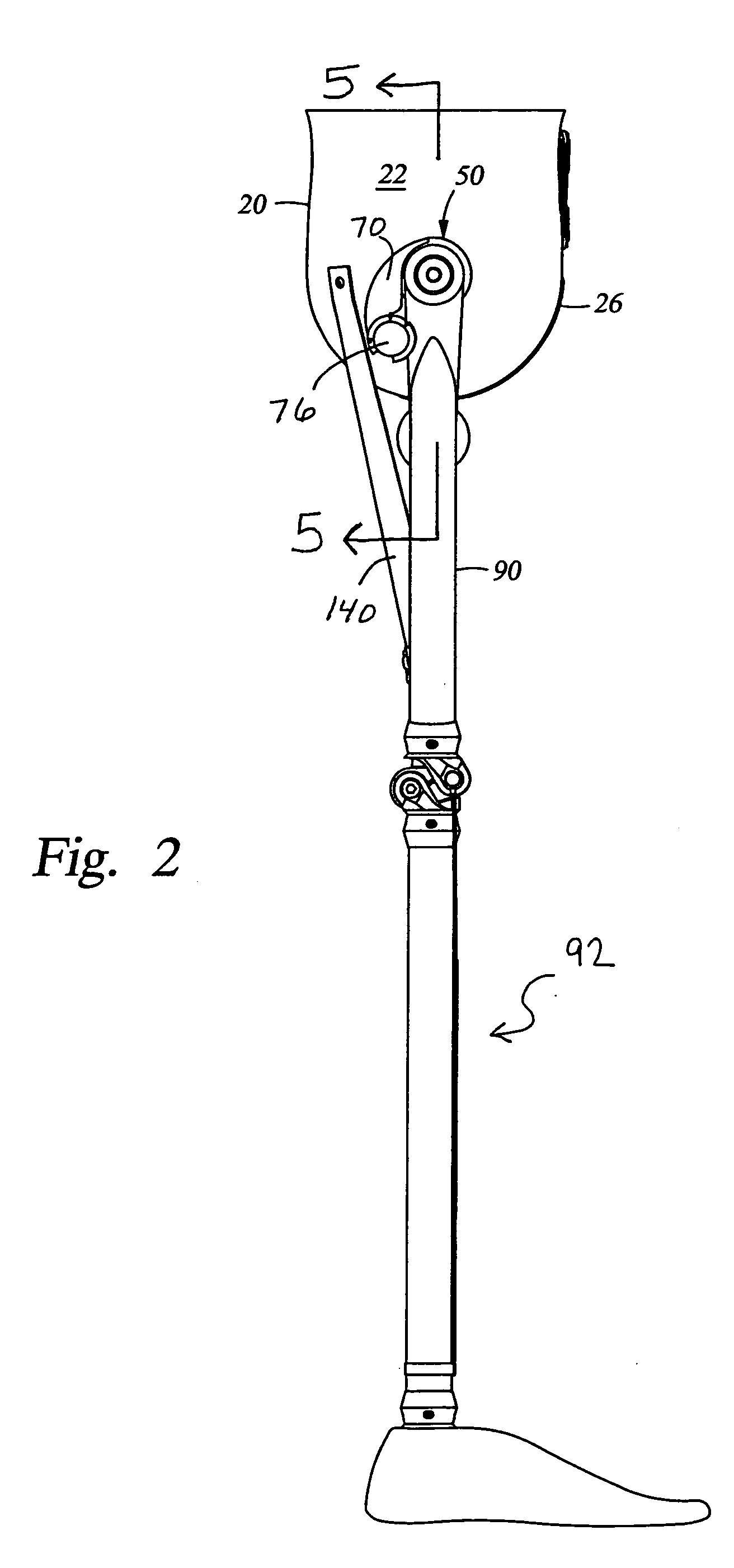
[0018] Referring now to FIGS. 2 and 3, the prosthetic hip 10 of the present invention includes a socket 20, a hip joint 50, and a load arm 100. Hip joint 50 is affixed to the side of socket 20 as described in detail below. Hip joint 50 serves to pivotally connect a femur 90 of an artificial leg 92 to socket 20. As further described below, in some embodiments, load arm 100 extends laterally from a point near the upper end of femur 90 to a point in a vertical plane that approximately intersects the natural hip joint.

[0019] Socket

[0020] As is known in the art, socket 20 is preferably constructed of fiber-reinforced plastic (FRP) and is preferably formed around a mold of the amputee's torso so that it provides a snug, customized fit. In this regard, any suitable technique for constructing and shaping socket 20 may be used. Socket 20 has an inner surface 21 and an outer surface 22. In a departure from conventional sockets, however, socket 20 includes a mount for hip joint 50 that is po...


PUM


Abstract

A prosthetic hip for supporting on a patient a prosthetic leg comprises a socket, a mount on the outer surface of the socket and defining a joint axis, the joint axis substantially coinciding with the natural axis of rotation of the patient's natural leg when rotated in a sagittal plane, and a first member adjustably affixed to the socket's outer surface. The first member includes an extension stop member and the upper end of the leg is pivotably mounted on the mount such that and pivoting of the leg in at least one direction is limited by the stop member. The prosthetic hip may also include a roller on a load arm extending medially from the upper leg end so as to engage the outer surface of the socket transmit a load from the socket directly to the prosthetic leg.

Description

TECHNICAL FIELD OF THE INVENTION [0001] The present invention relates generally to a prosthetic hip designed to provide a pivoting motion that closely resembles that of a natural hip joint. More particularly, the present invention relates to a prosthetic hip having a side pivot point and an aligned load point. BACKGROUND OF THE INVENTION [0002] When it is necessary to amputate a diseased or damaged leg from a human being, the amputation is typically performed in one of two ways. Hip disarticulation amputations are surgical procedures in which the leg is removed at the hip joint, leaving the pelvis substantially intact. Hemipelvectomy amputations are surgical procedures in which a portion of the pelvis is removed along with the leg. Amputees who have undergone either procedure often wish to be fitted with prosthetic equipment that will allow them to replicate at least a portion of the function of the missing limb. Typically, this entails creation of both a prosthetic hip joint and ar...

Claims


Application Information

Patent Timeline
IPC IPC(8): A61F2/00A61F2/50A61F2/60A61F2/64A61F2/78A61F2/80
CPCA61F2/605A61F2220/0041A61F2/80A61F2002/30405A61F2002/30433A61F2002/5018A61F2002/5039A61F2002/5043A61F2002/5055A61F2002/5067A61F2002/507A61F2002/607A61F2002/608A61F2002/7862A61F2220/0025A61F2/642
Inventor WILSON, MICHAEL T.
Owner WILSON MICHAEL T
Why Eureka
Try Eureka