Apparatus and method for measuring the weight of an occupant in a vehicle

a technology for measuring the weight of an occupant and a vehicle seat, which is applied in the direction of instruments, apparatus for force/torque/work measurement, tractors, etc., can solve the problems of not providing an accurate measurement of the weight of the occupant, the sensor the seat and any sensor coupled to the seat is subject to error-inducing loads, so as to prevent inaccurate readings of the occupant.

Inactive Publication Date: 2005-03-03
ROBERT BOSCH CORP
View PDF36 Cites 8 Cited by
  • Summary
  • Abstract
  • Description
  • Claims
  • Application Information

AI Technical Summary

Benefits of technology

[0004] Some embodiments of the invention provide an apparatus for measuring a load on a load-bearing platform. For example, specific embodiments of the invention provide an apparatus or bracket for coupling a seat to a floor of a vehicle and measuring the weight of an occupant on the seat. Certain embodiments of the invention are particularly useful at preventing inaccurate readings of an occupant's weight due to extraneous forces placed on the seat and the bracket. In other words, the present invention can isolate the vertical load placed on a seat (which is due primarily to the weight of the occupant) from other extraneous, non-vertical forces placed on the seat by accelerations and decelerations of the vehicle and the like. As will be described in greater detail below, some embodiments use one or more pivots, levers, and sensors to filter out non-vertical loads from vertical loads.

Problems solved by technology

Many of these devices, however, do not provide an accurate measure of the occupant's weight because additional forces other than the occupant's weight are also measured by the sensor.
Specifically, the seat and any sensor coupled to the seat is subject to error-inducing loads caused by forces in the X, Y, and Z directions and moments about the X, Y, and Z directions.
These error-inducing loads (or forces) can be transferred to the sensor and cause the sensor to generate incorrect information.

Method used


Image

  • Apparatus and method for measuring the weight of an occupant in a vehicle
  • Apparatus and method for measuring the weight of an occupant in a vehicle
  • Apparatus and method for measuring the weight of an occupant in a vehicle

Examples


first embodiment

[0034] Several embodiments of the present invention will be described below. Some features of each embodiment are similar and are therefore given similar reference numbers. For example, a feature labeled as element “9” in one embodiment, may be labeled as element “109,”“209,” etc. in other embodiments. Although some features may share a common number, it does not mean that the features are identical. Rather, it indicates that these features are similarly situated, share structural similarities, or perform similar functions. The features that are common to one or more embodiments will generally only be described once. Thus, it will be described in the first embodiment in which it appears. The descriptions of common elements will generally not be repeated in subsequent embodiments. Thus, reference to previous embodiments may be required in some instances to fully understand certain embodiments.

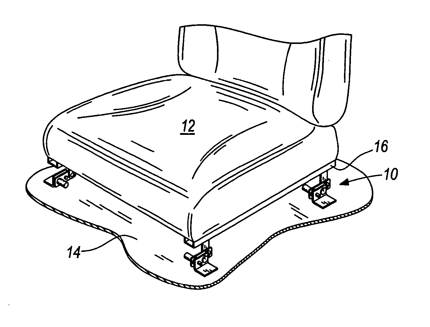
[0035]FIG. 1 illustrates a plurality of brackets 10 positioned below a seat 12 to support an...

sixth embodiment

[0063] By closing off the bifurcated portion 527 at both ends, the linkage 526 can be connected in a different manner with the As illustrated in FIG. 12, the linkage 527 is connected to the closed end of the bifurcated portion 527 with a fastener. Unlike the previous embodiment, the illustrated fastener of this embodiment has an axis that is substantially normal to the axis of the pivot 530. Such an arrangement can help reduce y-direction forces and moments about the x-axis (see FIG. 2) transferred to the lever 524. Consequently, this reduces the number of extraneous forces that need to be filtered by the remainder of the apparatus. This arrangement between the lever and the linkage can be utilized in other embodiments disclosed herein.

[0064] Although a pivot having a single axis is illustrated in the sixth embodiment, other connections between the linkage 526 and the lever 524 can be utilized. For example, a ball joint can be used in place of the pivot. A ball joint can prevent mo...

fourth embodiment

[0066] Each lever 624 is substantially identical and has a three portions: a first portion 661 located near a first corner of the seat, a second portion 662 located near a second corner of the seat, and a third portion 663 connecting the two portions 661, 662 together. The first and second portions 661, 662 are substantially identical. Therefore, only one will be discussed. The first portion 661 is substantially similar to the lever 324 of the Specifically, the first portion is split between a first segment 627 that is bifurcated and a second segment 628 adjacent the bifurcated portion. Like the previous embodiments, the pivot 630 and the seat are coupled to the first portion 661 along the bifurcated segment 627. However, unlike the previous embodiments, the third portion 663 of the lever 624 stretches underneath the seat from the first portion 661 located adjacent one side of the seat to the second portion 662 located adjacent an opposite side of the seat. Additionally, a tab 664 ...


PUM


Abstract

An apparatus and method for supporting a load-bearing platform (e.g., a seat) and measuring the weight of a load (e.g., an occupant) on the platform. The apparatus can include a base or support, a lever coupled to the support, and a sensor. The lever can be pivotally coupled to the support to allow pivotal movement of the lever with respect to the support in response to weight applied to the platform. The sensor can detect the force transmitted by the lever to determine the weight of the load on the platform. Furthermore, the lever can isolate the vertical load on the platform due to the weight of the load from other extraneous, non-vertical forces on the platform.

Description

FIELD OF THE INVENTION [0001] The present invention relates to an apparatus and method for measuring loads. Particularly, the invention relates to an apparatus and method for measuring a load on a load-bearing platform. More particularly, the invention relates to an apparatus and method for measuring the weight of an occupant sitting on a vehicle seat. BACKGROUND [0002] Automobiles are equipped with seat belts and airbags to provide safety for passengers. In recent years, there is a trend for controlling the operation of such safety devices according to the body weight of a passenger. For example, the amount of gas to be introduced into the airbag, an airbag inflating speed, or a pre-tension of the seat belt may be adjusted according to the weight of a passenger. To optimally use these safety devices, the weight of the seat's occupant must be measured. [0003] Several devices have been designed to measure the weight of the occupant while seated. Most of these devices use some form of...

Claims


Application Information

Patent Timeline
Patent Type & Authority Applications(United States)
IPC IPC(8): G01G19/414
CPCG01G19/4142
Inventor THAKUR, RAJEEVVANFLEET, CHADGOLSHTEYN, ALEKSANDR
Owner ROBERT BOSCH CORP
Why Eureka
Try Eureka