Winged digging tooth

Inactive Publication Date: 2005-03-10
H & L TOOTH
View PDF34 Cites 43 Cited by
  • Summary
  • Abstract
  • Description
  • Claims
  • Application Information

AI Technical Summary

Benefits of technology

[0003] Buckets of varying sizes and shapes are commonly arranged in operable combination with backhoes, front loaders, excavators and related earthworking equipment. Most buckets include areas, i.e., the leading bucket edge, bucket side walls, etc., which are exposed and, thus, are highly susceptible to wear, especially when the bucket is used in abrasive and rocky environments. In many bucket designs, a one-piece, tr

Problems solved by technology

Most buckets include areas, i.e., the leading bucket edge, bucket side walls, etc., which are exposed and, thus, are highly susceptible to wear, especially when the bucket is used in abrasive and rocky environments.
A vast preponderance of ground engaging teeth, however, are designed as two-part systems.
Regardless of the particular design of the digging tooth, be it of one-piece design or configured as a two-part system or assembly, wear and deterioration of the leading bucket edge is a very serious concern.
The leading or cutting edge of the bucket is typically quite hard to protect against impacts, wear, and undue stress associated with typical excavating operations, protection of the leading or cutting bucket edge remains of paramount importance.
Unfortunately, the front cutting edge of the digging tooth provides only a limited ground fracturing zone in advance of the bucket cutting edge.
As such, known digging tooth designs have limited

Method used


Image

  • Winged digging tooth
  • Winged digging tooth
  • Winged digging tooth

Examples


Embodiment Construction

[0084] The present invention is susceptible of embodiment in multiple forms and there is shown in the drawings and will hereinafter be described various embodiments of the invention, with the understanding the present disclosure sets forth exemplifications of the invention which are not intended to limit the invention to the specific embodiments illustrated and described.

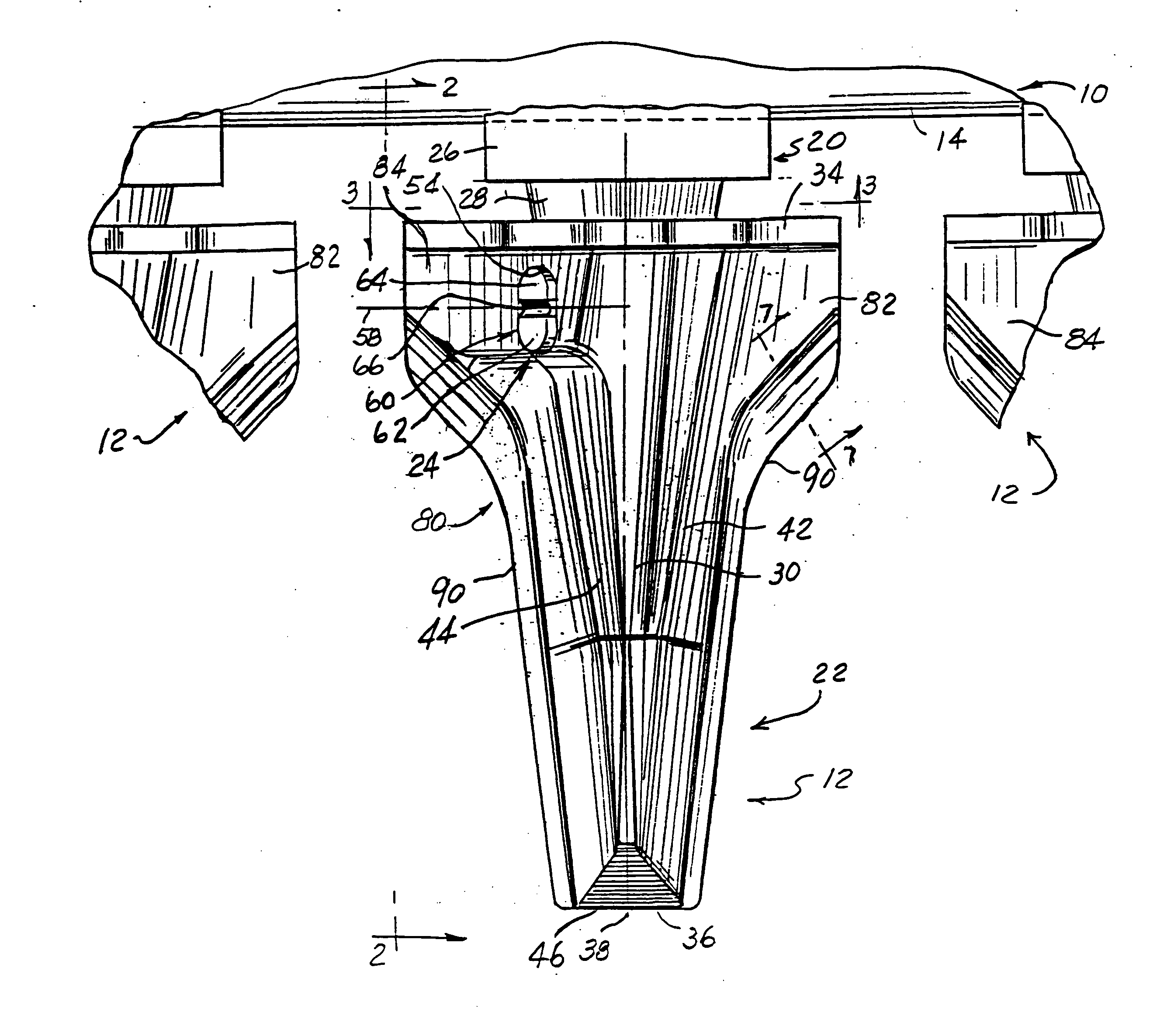
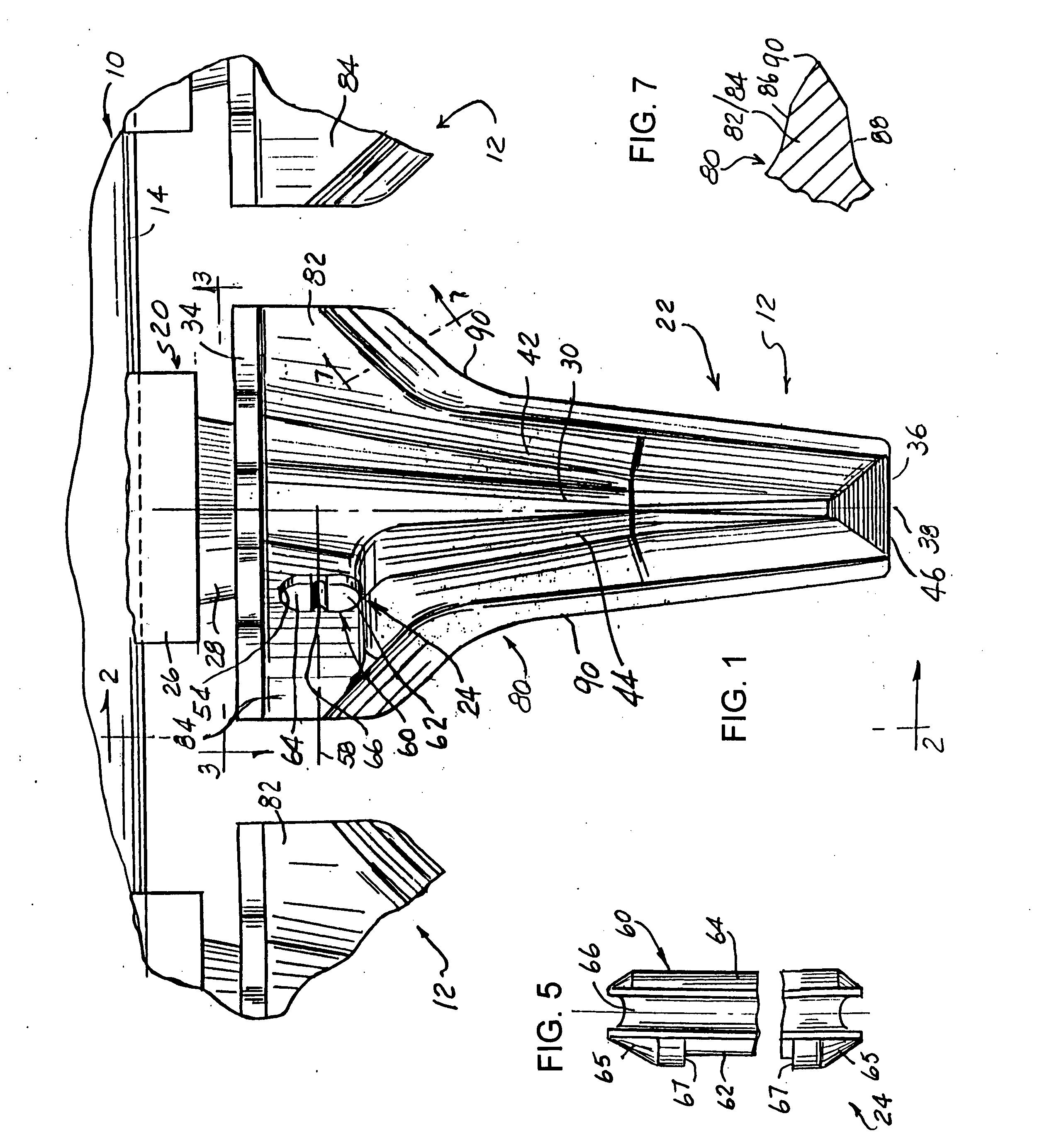
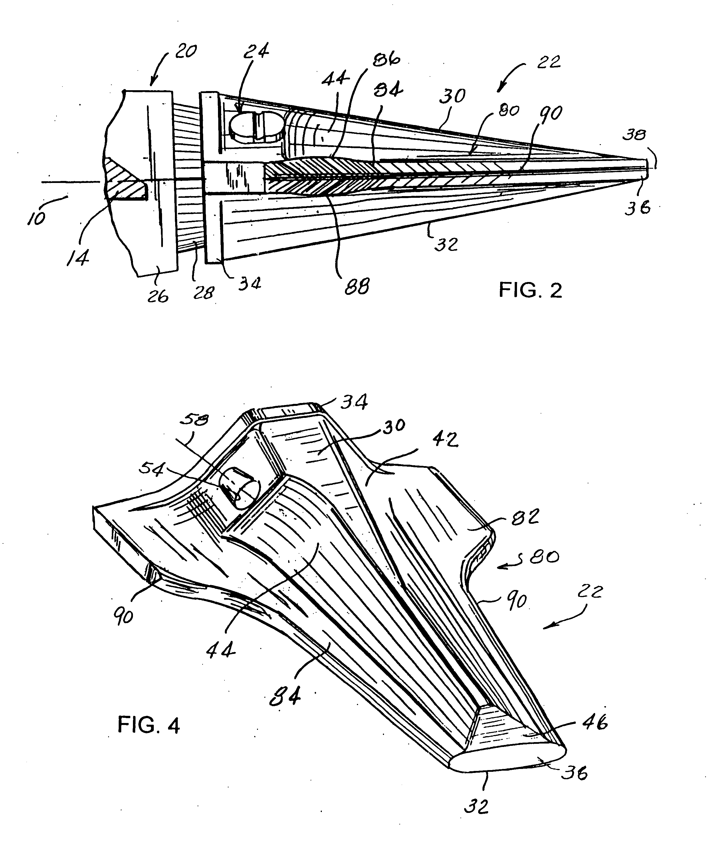
[0085] Referring now to the drawings, wherein like reference numerals indicate like parts throughout the several views, there is shown a ground engaging implement, such as a bucket or the like, generally indicated by numeral 10, with a series of digging tooth assemblies 12 arranged in side-by-side relation relative to each other. Bucket 10 is of the type commonly arranged in combination with a backhoe, front loader, excavator or related earth working implement. As shown, bucket 10 includes a base edge or lip 14 extending across and typically welded to the remainder of the bucket 10. As will be appreciated, the lead...


PUM


Abstract

A digging tooth adapted to extend forward from a leading edge of a bucket or the like. The digging tooth has a forward end, with an edge extending thereacross, and a rear end. The digging tooth further includes wing structure formed integral with the digging tooth and extending from a surface on the tooth so as to provide the bucket with enhanced ground penetration capability while concomitantly shielding ground engaging components disposed rearwardly of a rear end of the digging tooth against wear and, thus, potentially extending the useful wear life of such components.

Description

RELATED APPLICATIONS [0001] This application claims the benefit of provisional Application Ser. No. 60 / 501,381, filed Sep. 9, 2003.FIELD OF THE INVENTION [0002] The present invention generally relates to ground engaging implements and, more particularly, to a digging tooth adapted to be secured to and project forward from a leading or forward edge of a bucket or the like. SUMMARY OF THE INVENTION [0003] Buckets of varying sizes and shapes are commonly arranged in operable combination with backhoes, front loaders, excavators and related earthworking equipment. Most buckets include areas, i.e., the leading bucket edge, bucket side walls, etc., which are exposed and, thus, are highly susceptible to wear, especially when the bucket is used in abrasive and rocky environments. In many bucket designs, a one-piece, transversely elongated base edge or lip is welded to other bucket walls and serves as a leading edge for the bucket. The bucket edge is frequently provided with a sharpened or be...

Claims


Application Information

Patent Timeline
IPC IPC(8): E02F9/28
CPCE02F9/2841E02F9/2883E02F9/2858E02F9/28
Inventor CLENDENNING, CHARLESLAUNDER, BRIAN L.
Owner H & L TOOTH
Why Eureka
Try Eureka