Under-cabinet mount for flat-panel displays

a flat-panel display and under-cabinet technology, applied in the field of display mounts, can solve the problems of difficult operation, awkward devices including latches or detent mechanisms for positioning the display, and the mounts for flat-panel displays have not been entirely satisfactory, so as to achieve easy and smooth adjustment of the display position, the effect of simple operation

Inactive Publication Date: 2005-03-10
LEGRAND AV INC
View PDF25 Cites 60 Cited by
  • Summary
  • Abstract
  • Description
  • Claims
  • Application Information

AI Technical Summary

Benefits of technology

[0008] The current invention meets the need of the industry for an adjustable, folding mount for attaching a flat panel display to a horizontal element of a fixed structure, that is relatively simple to operate and provides easy and smooth adjustability of the display position. According to an embodiment of the invention, the mount includes a mount portion adapted to attach to a horizontal element of a fixed structure, and a swing arm having one end operably coupled to the mount portion. The swing arm is selectively positionable along a path of travel between a folded position proximate the horizontal element of the fixed structure and an extended position wherein the swing arm depends downwardly from the horizontal element of the fixed structure. A device interface portion operably couples the other end of the swing arm and the flat panel display. Further, the mount includes friction means arranged to apply a first frictional resistance force opposing positioning of the swing arm toward the extended position, and a second frictional resistance force opposing positioned of the arm toward the folded position, the first frictional resistance force being greater than the second frictional resistance force.

Problems solved by technology

Previous mounts for flat panel displays have not been entirely satisfactory.
Some of these previous mounting devices including catches, latches or detent mechanisms for positioning the display are awkward, difficult to operate and may not provide the capability of positioning the display at desired viewing angles.
These friction devices may enable positioning the display at any desired angle, but are sometimes difficult to position due to the relatively large amount of frictional force needed to hold the display in the stowed position.
Such devices may stick and impart a jerky motion when the display is being positioned toward the stowed position, so that the weight of the display is not being supported by the friction device.

Method used


Image

  • Under-cabinet mount for flat-panel displays
  • Under-cabinet mount for flat-panel displays
  • Under-cabinet mount for flat-panel displays

Examples


Embodiment Construction

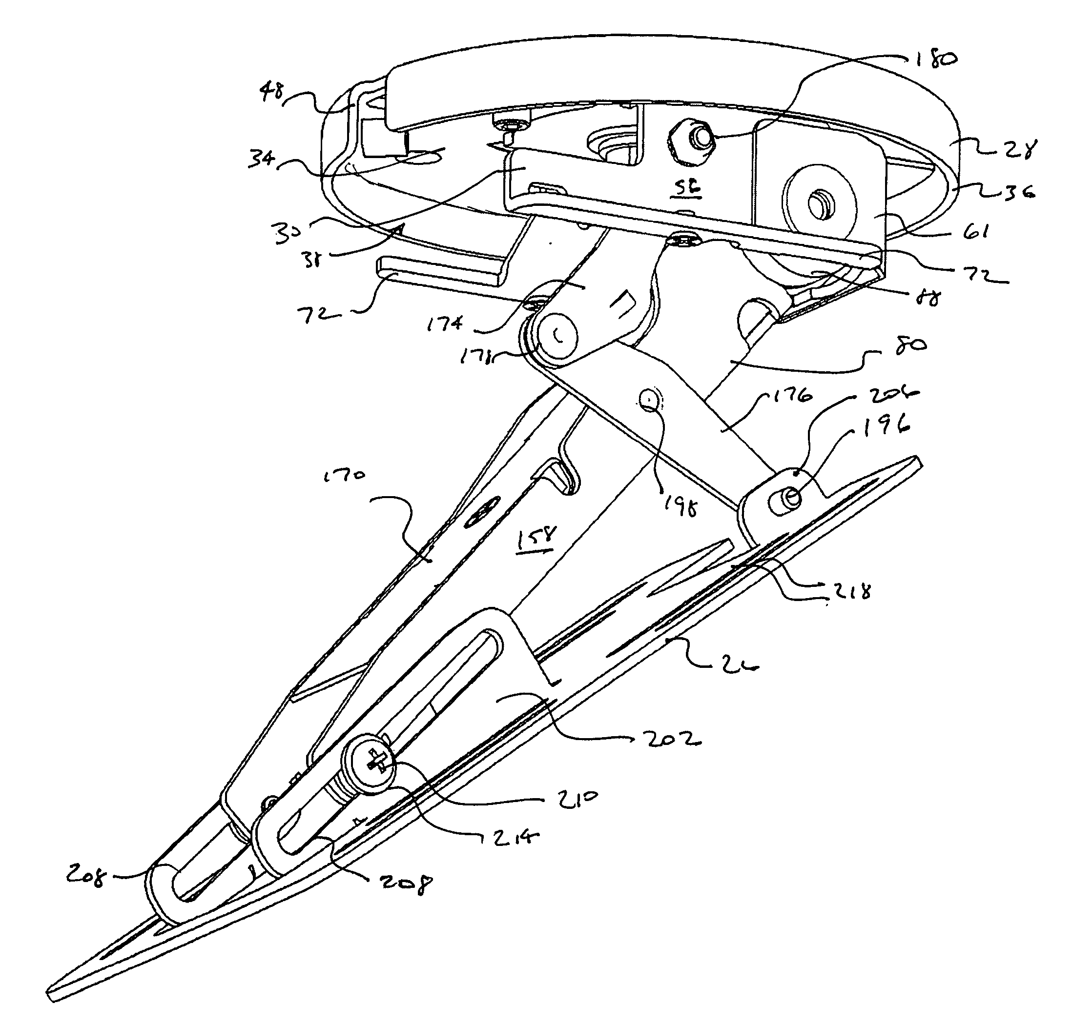
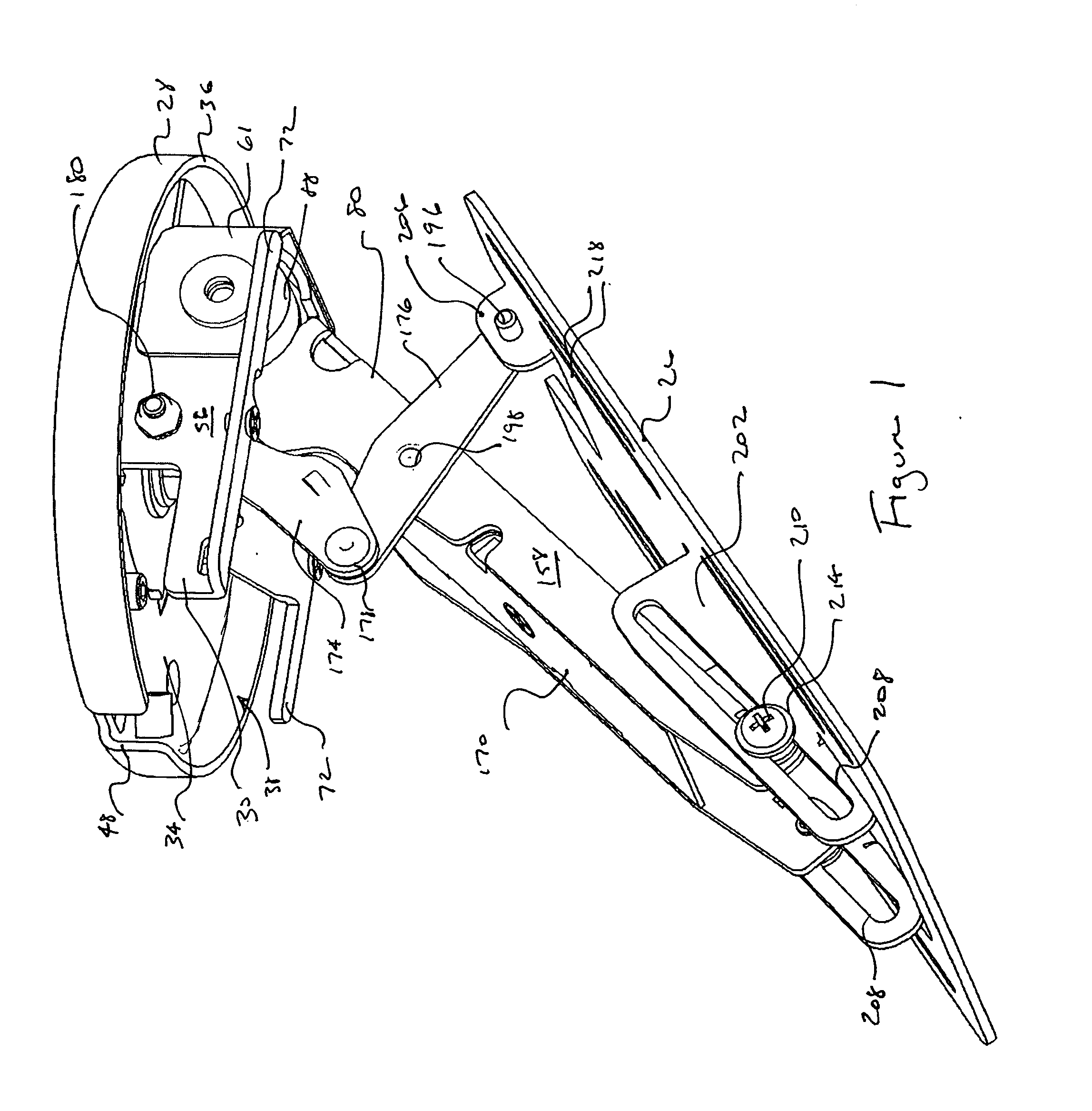
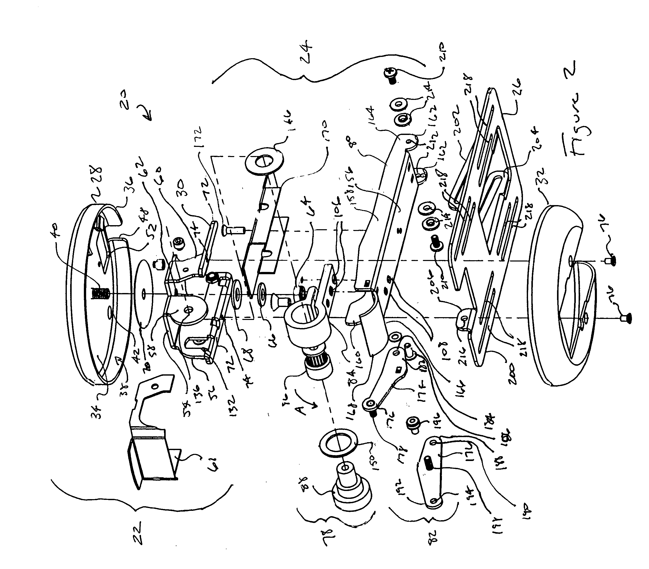
[0024] A flat-panel display mount 20 according to the present invention generally includes mount bracket assembly 22, arm assembly 24, and device interface bracket 26. Mount bracket assembly 22 generally includes turret base 28, hinge body 30, and turret cover 32. Turret base 28 has a generally planar body portion 34 with a downwardly projecting skirt 36 defining recess 38. Threaded stud 40 projects from body portion 34 into recess 38. Apertures 42 are provided in body portion 34 to receive fasteners (not depicted) for fastening mount 20 to a fixed structure, such as the underside 44 of a cabinet 46. Wire notch 48 may be provided in skirt 36 to enable wires from the flat panel display 50, such as video, sound and antenna wires, to be routed through mount 20. Larger aperture 52 may also be provided in body portion 34 to enable such wires to be routed through the fixed structure if desired.

[0025] Hinge body 30 is generally U-shaped with a central portion 54 and projecting side portio...


PUM


Abstract

An adjustable, folding mount for attaching a flat panel display to a fixed structure. The mount includes a portion adapted to attach to an element of a fixed structure, and a swing arm operably coupled thereto. The swing arm is selectively positionable along a path of travel between a folded position proximate the fixed structure and an extended position wherein the swing arm depends downwardly from the fixed structure. A device interface portion operably couples the other end of the swing arm and the flat panel display. The mount includes friction means arranged to apply a first frictional resistance force opposing positioning of the swing arm toward the extended position, and a second frictional resistance force opposing positioning of the arm toward the folded position, the first frictional resistance force being greater than the second frictional resistance force.

Description

RELATED APPLICATIONS [0001] This application claims the benefit of U.S. Provisional Patent Application Ser. No. 60 / 489,419, filed Jul. 23, 2003, entitled “UNDER-CABINET MOUNT FOR FLAT PANEL DISPLAYS”, and hereby fully incorporated herein by reference.FIELD OF THE INVENTION [0002] The present invention relates generally to display mounts. More particularly, the present invention relates to a mount for mounting a flat-panel display on a fixed structure such as underneath a cabinet or the like. BACKGROUND OF THE INVENTION [0003] Mounting devices for electronic displays including flat panel display devices are generally known in the art. In some instances, such mounts are used in a restricted space and keep a surface free of obstruction while allowing a person to view the display positioned above the surface. Hughes discloses such an apparatus for mounting a television under a cabinet in U.S. Pat. No. 4,580,754. U.S. Pat. No. 4,666,113, U.S. Pat. No. 6,341,754, and U.S. Pat. No. 5,333,8...

Claims


Application Information

Patent Timeline
Patent Type & Authority Applications(United States)
IPC IPC(8): F16M11/04
CPCF16M11/04F16M11/10Y10S248/917F16M11/38F16M13/02F16M11/2021
Inventor DITTMER, JAY
Owner LEGRAND AV INC
Why Eureka
Try Eureka