Chair with lumbar support and conforming back
- Summary
- Abstract
- Description
- Claims
- Application Information
AI Technical Summary
Benefits of technology
Problems solved by technology
Method used
Image
Examples
first embodiment
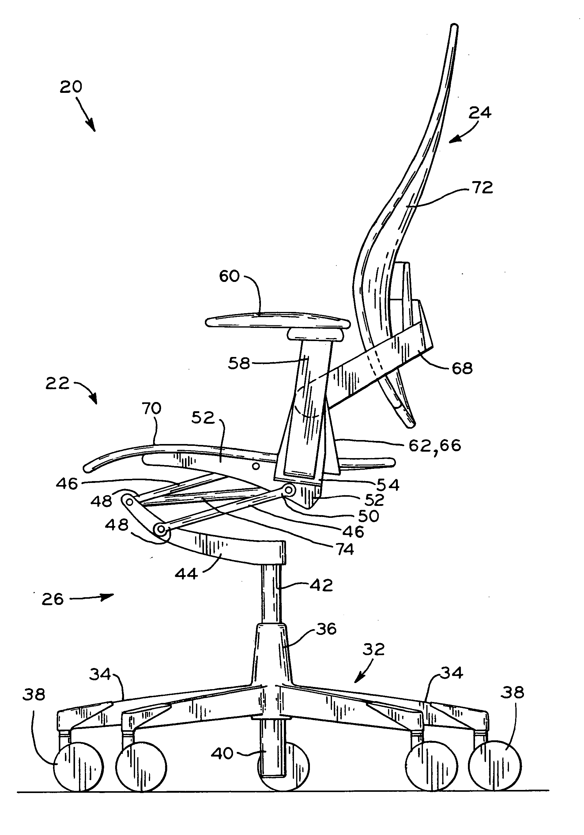
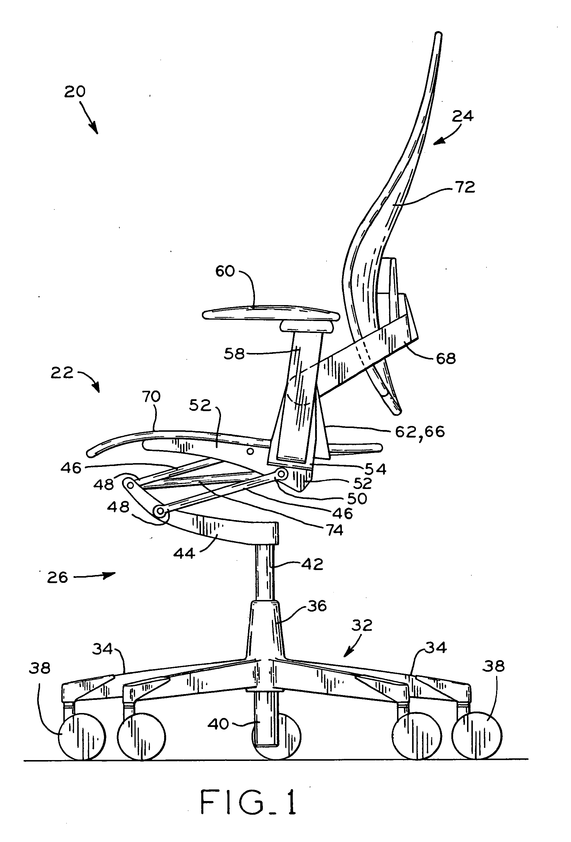
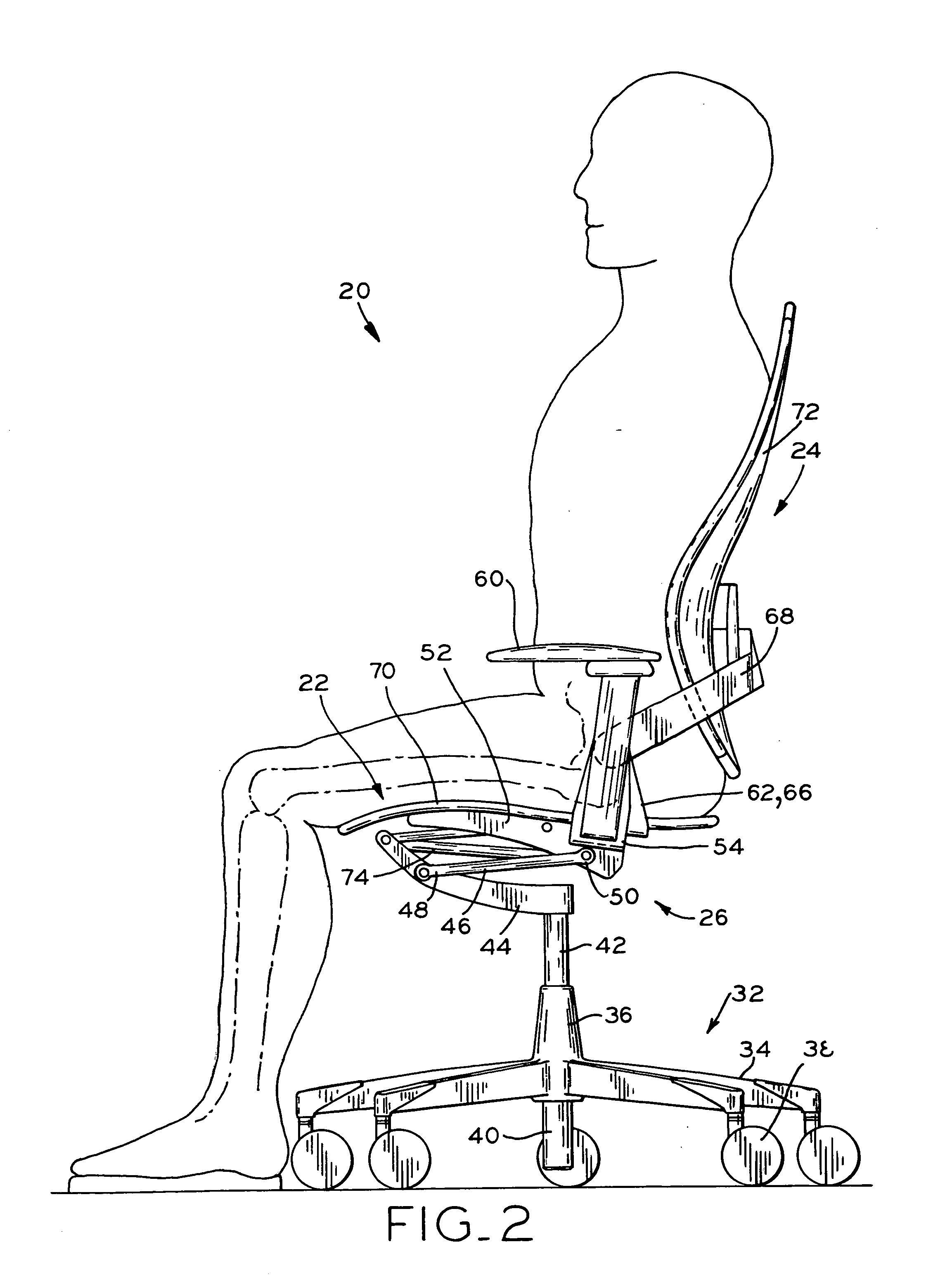
[0037] Referring to FIG. 4, backrest 72 is shown. Backrest 72a includes backrest frame 68 having a pair of support arms 82 with first ends 84 moveably connected to upper ends 66 of L-shaped brackets 62. Support arms 82 each include second ends 86 opposite first ends 84 which include support portions 88 projecting upwardly therefrom. Support portions 88 of support arms 82 are attached to rigid portion 80a of backrest 72a in a suitable manner, with rubber bushings 92 therebetween. Support portions 88 of lumbar support arms 82 and rubber bushings 92 provide substantially rigid flex points or flex joints which, in cooperation with the flexible portions of backrest 72, allow backrest 72 to ergonomically conform to a seated user, as described in further detail below.
[0038] Backrest 72a includes back support surface 94a defined by rigid portion 80a and flexible portion 90a. Rigid portion 80a has a generally inverted T-shape, including base section 96a and a single arm section 98a projectin...
second embodiment
[0050] backrest 72, backrest 72b, is shown in FIG. 5, and is somewhat similar to backrest 72a. Backrest 72b includes back support surface 94b defined by rigid portion 80b and flexible portion 90b. Rigid portion 80b is generally U-shaped, including base section 96b and a pair of arm sections 98b projecting upwardly therefrom. Flexible portion 90b is disposed around the periphery of rigid portion 80b and in between rigid portions 90b. Backrest 72b is supported by backrest frame 68 including a single support arm 106, having first ends 108 movably attached to upper ends 66 of L-shaped brackets 62. Joint mechanism 100 operates similar to the joint mechanism 100 described above with respect to backrest 72a. Joint mechanism 100 of backrest 72b may also include tension adjustment lever 102, which is provided for adjusting the pre-tension of the energy source of joint mechanism 100, which supports support arm 106 and backrest 72b and allows movement of same between the more upright position ...
third embodiment
[0052] backrest 72 is shown in FIGS. 6A-6D. Backrest 72c includes back support surface 94c defined by a pair of rigid portions 80c which are disposed along respective sides of backrest 72c, and flexible portion 90c which is disposed around the peripheries of rigid portions 80c and which defines the remainder of backrest 72c. As may be seen in FIGS. 6A and 6D, rigid portions 80c and flexible portion 90c have a substantially equal thickness, and together define a substantially thinly-profiled backrest 72c. Backrest 72c is supported by backrest frame 150 having central portion 152 and end portions 154 attached to the upper ends 56 of U-shaped arm support 54. Support arm 156 includes central portion 158 attached to central portion 152 of backrest frame 150, and also includes end portions 160 attached to rigid portions 80c of backrest 72c at flex joints 162, as described below. The attachment of central portion 158 of support arm 156 to central portion 152 of backrest frame 150 may be a ...
PUM
 Abstract
Description
Claims
Application Information
 - R&D
- Intellectual Property
- Life Sciences
- Materials
- Tech Scout
- Unparalleled Data Quality
- Higher Quality Content
- 60% Fewer Hallucinations
Browse by: Latest US Patents, China's latest patents, Technical Efficacy Thesaurus, Application Domain, Technology Topic, Popular Technical Reports.
© 2025 PatSnap. All rights reserved.Legal|Privacy policy|Modern Slavery Act Transparency Statement|Sitemap|About US| Contact US: help@patsnap.com


