Supercharge Your Innovation With Domain-Expert AI Agents!

Optical performance monitoring using a semiconductor optical amplifier

Inactive Publication Date: 2005-03-10
LUCENT TECH INC +1
View PDF22 Cites 11 Cited by
  • Summary
  • Abstract
  • Description
  • Claims
  • Application Information

AI Technical Summary

Benefits of technology

[0008] Problems in the prior art are addressed, in accordance with the principles of the present invention, by an optical device having a semiconductor optical amplifier (SOA) coupled to an optical filter, which device may be used for optical performance monitoring. One embodiment of the invention provides an optical regenerator/monitor (RM), in which an SOA is used both for optical regeneration of a communication signal applied to the RM and for evaluation of the quality of that signal. The RM has (i) a 2R regenerator, which includes the SOA and an optical filter, and (ii) a relatively simple signal processor configured to receive optical signals from two or more sampling points located at the regenerator. In one configuration, the processor evaluates the quality of the communication signal by comparing optical power tapped from the input and output of the regenerator. The RM, so configured, can be used, for example, to monitor chromatic dispersion and/or optical noise in the communication signal. Advantageously, a single RM of the invention can perform network functions of two separate prior-art devices, a regenerator and an optical performance monitor.
[0009] According to one embodiment, the present invention is a device, comprising: a semiconductor optical amplifier (SOA) adapte

Problems solved by technology

However, one disadvantage of such an OPM is that it typically requires high-speed electronics.
Furthermore, at relatively high bit rates, e.g., about 40 Gb / s, either the sensitivity or bandwidth of the electronics may be insufficient to accurately and / or cost-effectively measure the impairments.
However, one problem with such optical-domain-based OPMs is that they often require relatively expensive optical components, such as nonlinear crystals, interferometers, tunable filters, etc.

Method used


Image

  • Optical performance monitoring using a semiconductor optical amplifier
  • Optical performance monitoring using a semiconductor optical amplifier
  • Optical performance monitoring using a semiconductor optical amplifier

Examples


Embodiment Construction

[0021] Reference herein to “one embodiment” or “an embodiment” means that a particular feature, structure, or characteristic described in connection with the embodiment can be included in at least one embodiment of the invention. The appearances of the phrase “in one embodiment” in various places in the specification are not necessarily all referring to the same embodiment, nor are separate or alternative embodiments mutually exclusive of other embodiments.

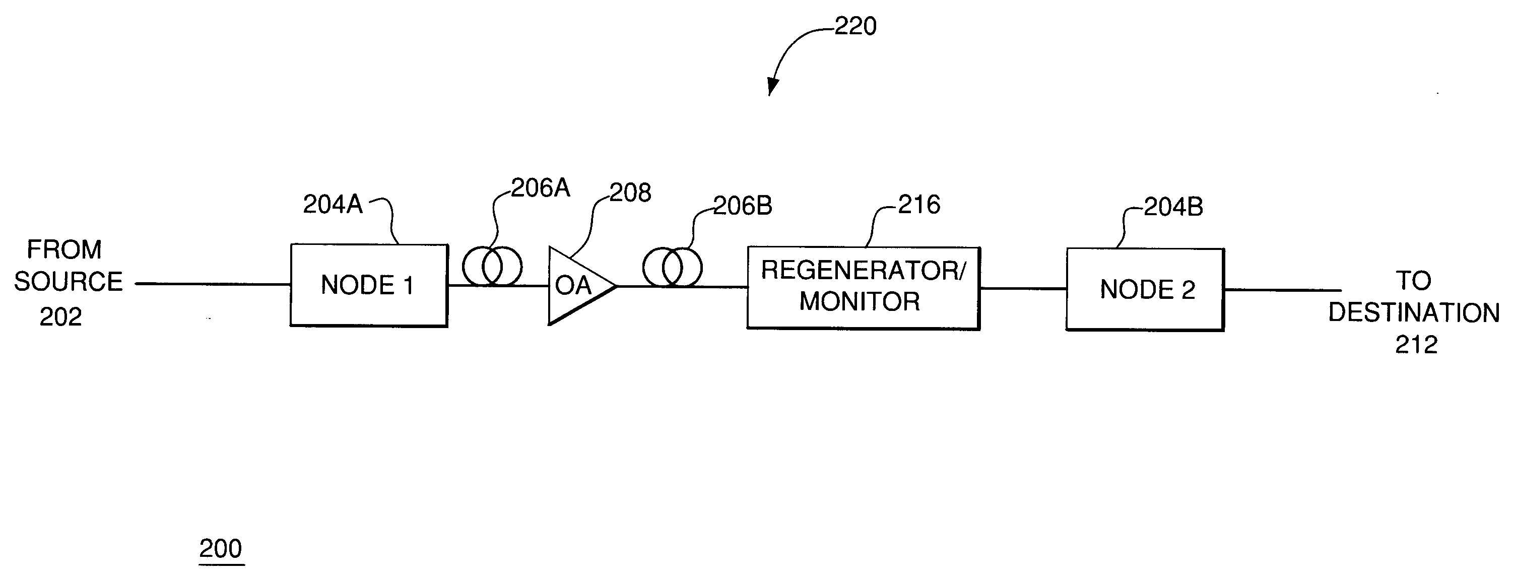
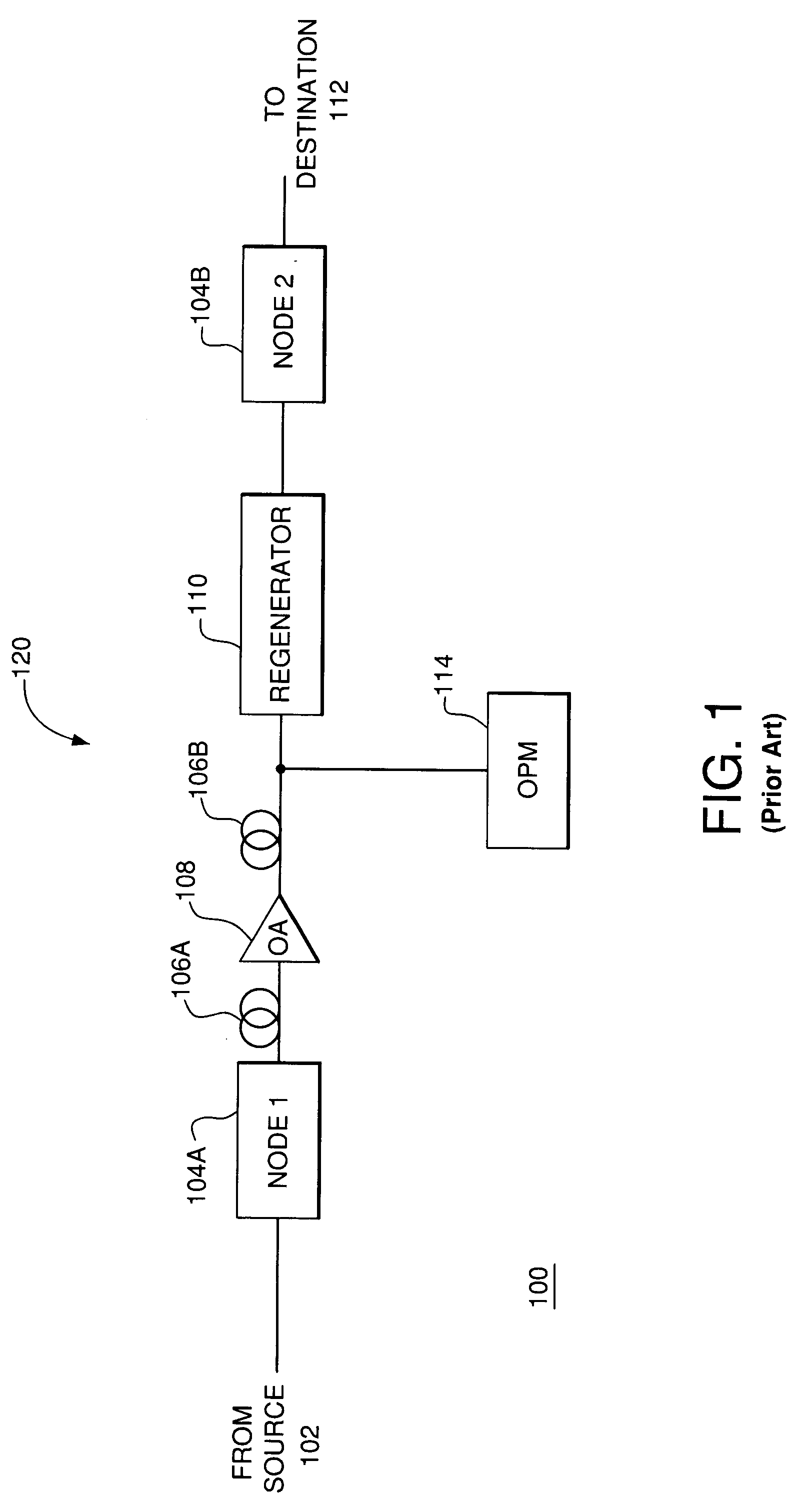
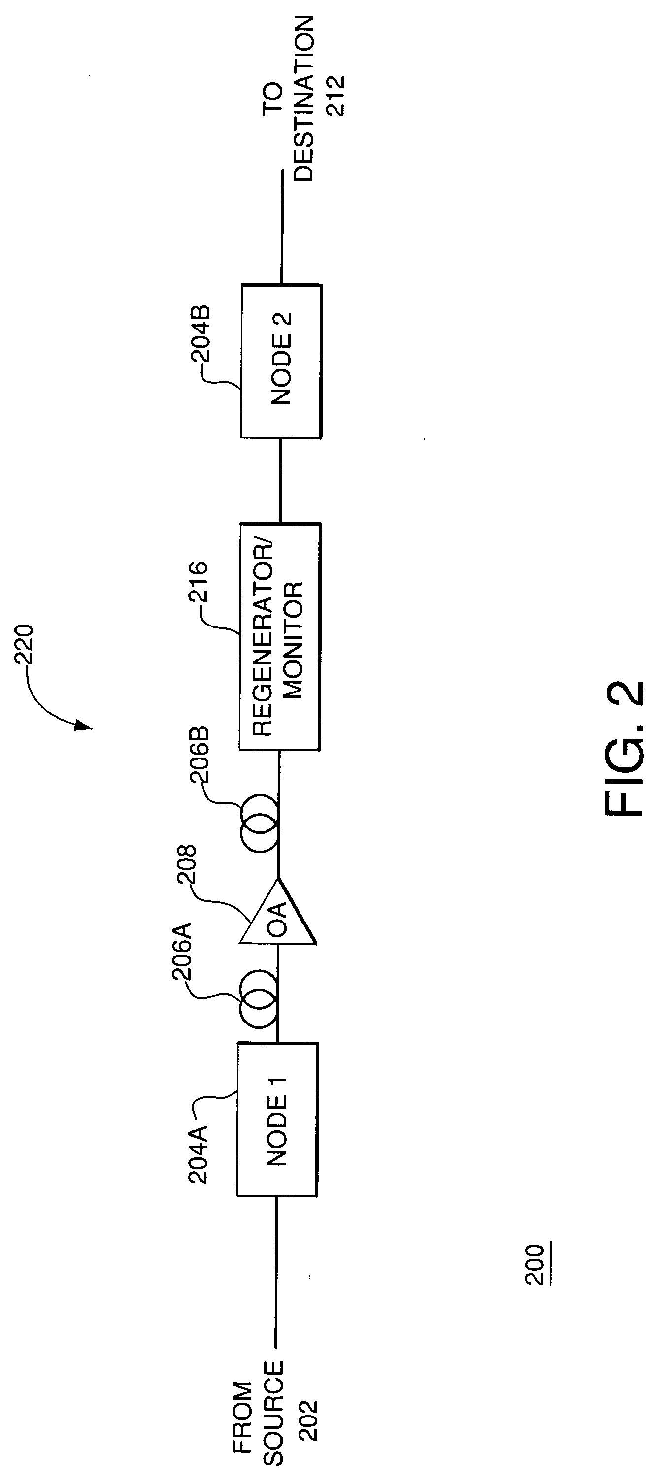
[0022]FIG. 2 shows a block diagram of a fiber-optic network 200 according to one embodiment of the present invention. Network 200 is analogous to network 100 of FIG. 1 with analogous elements of the two networks marked with labels having the same last two digits. However, one difference between networks 200 and 100 is that network 200 employs a novel regenerator / monitor (RM) 216, which performs functions analogous to those of the combination of regenerator 110 and OPM 114 in network 100. As will be explained below, some optical c...


PUM


Abstract

An optical device having a semiconductor optical amplifier (SOA) coupled to an optical filter, which device may be used for optical performance monitoring. One embodiment of the invention provides an optical regenerator / monitor (RM), in which an SOA is used both for optical regeneration of a communication signal applied to the RM and for evaluation of the quality of that signal. The RM has (i) a 2R regenerator, which includes the SOA and an optical filter, and (ii) a relatively simple signal processor configured to receive optical signals from two or more sampling points located at the regenerator. In one configuration, the processor evaluates the quality of the communication signal by comparing optical power tapped from the input and output of the regenerator. The RM, so configured, can be used, for example, to monitor chromatic dispersion and / or optical noise in the communication signal. Advantageously, a single RM of the invention can perform network functions of two separate prior-art devices, a regenerator and an optical performance monitor.

Description

BACKGROUND OF THE INVENTION [0001] 1. Field of the Invention [0002] The present invention relates to optical communication systems and, more specifically, to monitoring the performance of such systems. [0003] 2. Description of the Related Art [0004] Fiber optic networks are widely used for data transmission in modem communication systems. Due to increasing data traffic volumes, monitoring and management of networks become increasingly important. For example, such monitoring may include a measurement at a particular point in the network of the quality of an optical signal corresponding to one or more optical communication channels. The optical signal may be analyzed for various impairments, e.g., timing jitter, noise level, chromatic dispersion, and the like. Obtained information may then be used to improve the performance of the network, for example, if certain impairments exceed a tolerable level. [0005]FIG. 1 shows a block diagram of a representative fiber-optic network 100 config...

Claims


Application Information

Patent Timeline
IPC IPC(8): H01S3/00H01S3/067H01S3/094H01S3/10H04B10/02H04B10/08H04B10/17
CPCH01S3/005H01S3/0078H01S3/067H01S3/094003H04B10/299H04B10/07951H04B10/07953H04B10/0797H04B10/2914H01S3/10007
Inventor KILPER, DANIEL C.LEUTHOLD, JUERGVORREAU, PHILIPP
Owner LUCENT TECH INC
Features
  • R&D
  • Intellectual Property
  • Life Sciences
  • Materials
  • Tech Scout
  • Unparalleled Data Quality
  • Higher Quality Content
  • 60% Fewer Hallucinations
Learn More