Supercharge Your Innovation With Domain-Expert AI Agents!

Ring network system, node device, and protection band testing method for the ring network system

a technology of ring network system and node device, which is applied in the direction of data switching network, frequency-division multiplex, instruments, etc., can solve the problems of only evaluating the communication quality of such channels, no means for creating paths for checking and inability to evaluate the communication quality of channels in the protection band. to achieve the effect of preventing communication quality and checking communication quality

Inactive Publication Date: 2007-09-20
FUJITSU LTD
View PDF2 Cites 4 Cited by
  • Summary
  • Abstract
  • Description
  • Claims
  • Application Information

AI Technical Summary

Benefits of technology

[0019]The present invention makes it possible to provide a ring network system that includes a means for setting a path for checking the communication quality of a protection band and is capable of creating, in the protection band, a ring path starting at the first node device, passing through the second node devices, and ending at the first node device. In the ring network system, a test signal generation unit of the first node device sends out test signals to the ring path created in the protection band, and a test signal measurement unit of the first node device performs measurements on the test signals. The communication quality of the protection band can thus be evaluated.
[0021]According to this aspect, it is possible to provide a ring network system capable of creating a path for checking the communication quality of a protection band when a destination address and a source address in APS bytes received by a node device of the ring network system are the same.
[0022]The present invention makes it possible to check the communication quality of a protection band of a ring network system. Therefore, when a transmission band is switched from a working band to a protection band for line protection in the case of a line failure, the occurrence of another line failure after the line switching due to degradation in the communication quality of the protection band can be prevented.

Problems solved by technology

However, channels in the protection band are defined as “unused” and there is no means for creating a path for checking the communication quality of the channels.
Therefore, the communication quality of channels in the protection band cannot be evaluated.
The communication quality of such channels can only be evaluated when the channels are defined as being in the working band after the completion of switching operation performed due to a line failure.

Method used


Image

  • Ring network system, node device, and protection band testing method for the ring network system
  • Ring network system, node device, and protection band testing method for the ring network system
  • Ring network system, node device, and protection band testing method for the ring network system

Examples


first embodiment

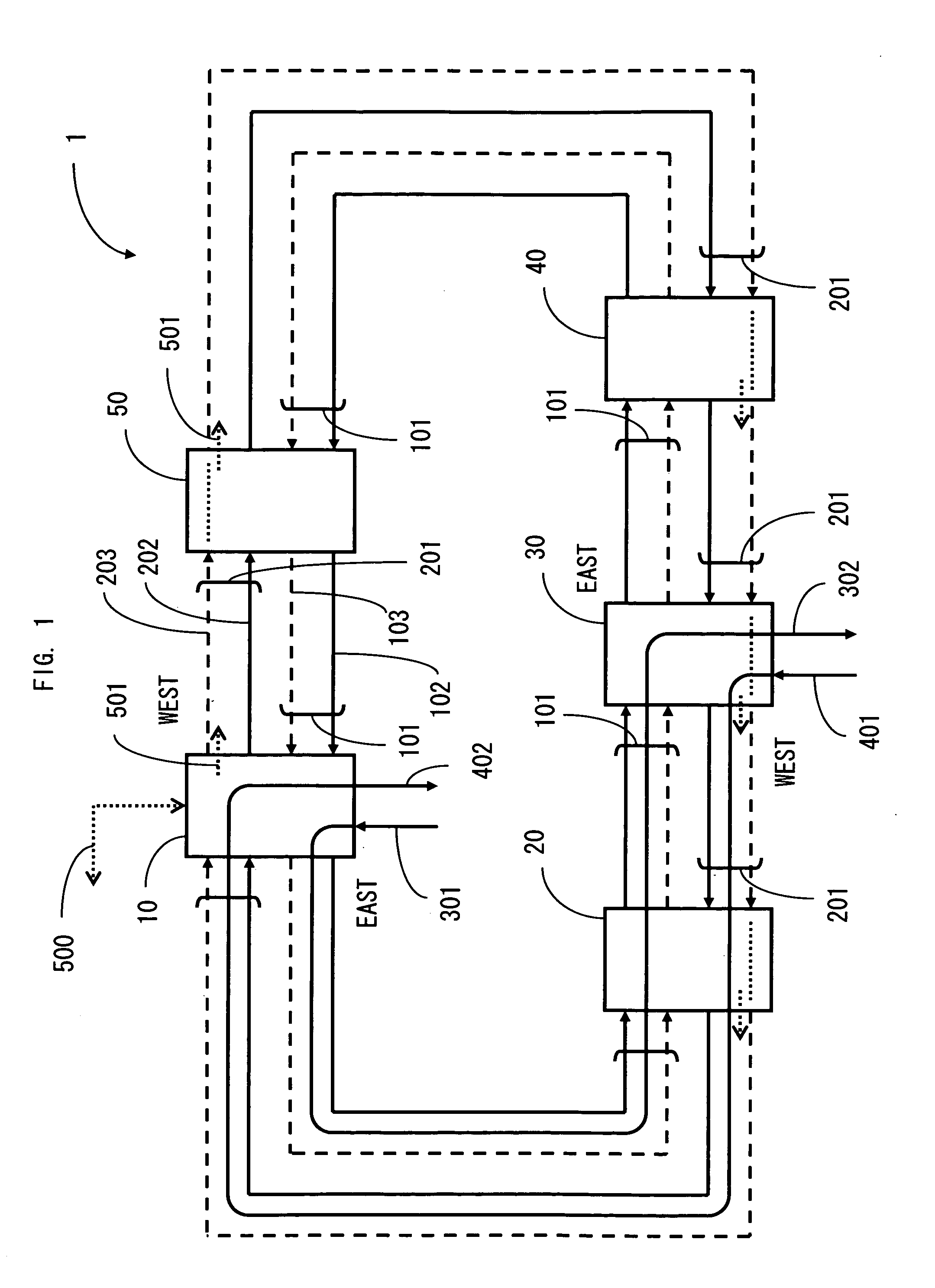
[0035]FIG. 1 illustrates an exemplary ring network system (ring network system 1) of the present invention. An EAST line 101, which is typically an optical fiber, is a transmission line for connecting node devices 10, 20, 30, 40, and 50 in EAST direction in a ring configuration. A WEST line 201, which is typically an optical fiber, is a transmission line for connecting the node devices 10, 20, 30, 40, and 50 in WEST direction in a ring configuration. A working band 102 and a protection band 103 are provided for signals transmitted over the EAST line 101. The working band 102 is provided for current use and the protection band 103 is provided for backup. Likewise, a working band 202 and a protection band 203 are provided for signals transmitted over the WEST line 201. The working band 202 is provided for current use and the protection band 203 is provided for backup. An ADD line 301 is added at the node device 10. A DROP line 302 is dropped at the node device 30. Likewise, an ADD lin...

second embodiment

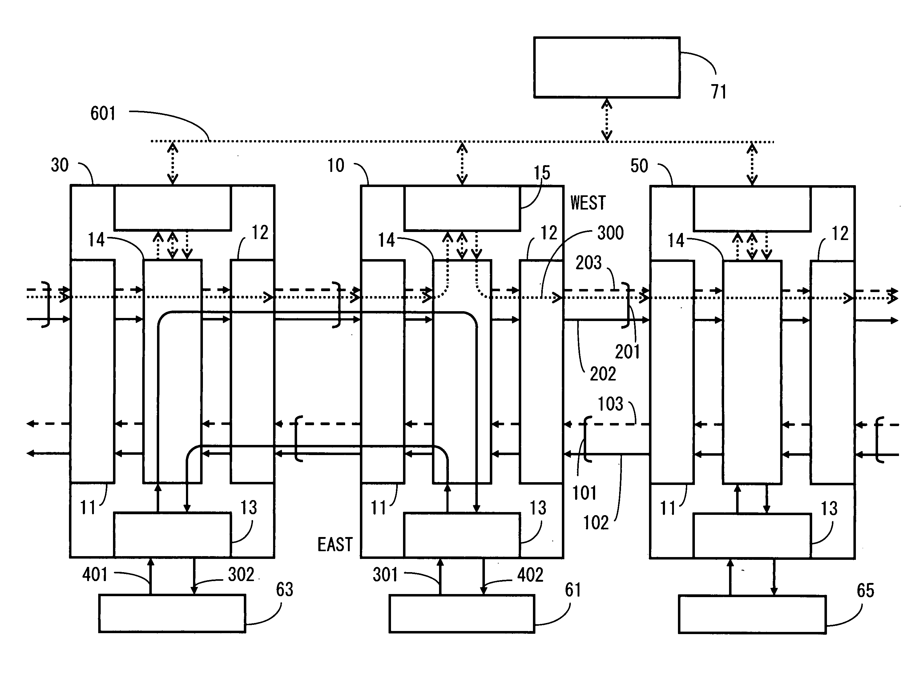
[0051]FIG. 4 is a diagram (1) illustrating exemplary operation of node devices. Of all the node devices 10 to 50 in the ring network system 1 illustrated in FIG. 1, the node devices 20 and 40 are omitted in FIG. 4. Intra-office devices 61, 63, and 65 are connected to the node devices 10, 30, and 50, respectively, within the corresponding offices (stations). An NMS 71 controls the node devices 10, 30, and 50 and the like. Each of the node devices 10, 30, and 50 includes line interfaces 11 and 12, an intra-office line interface 13, an ADM unit 14, and a test controller 15. A control / response signal 601 interfaces between the NMS 71 and the node device 10. Although FIG. 4 illustrates the connection between the NMS 71 and the node device 10 only, the NMS 71 is connected to either of the node devices 30 and 50 in the same manner as to the node device 10.

[0052]As in the case of the ring network system illustrated in FIG. 1 or FIG. 8, paths for the intra-office device 61 and the node devic...

third embodiment

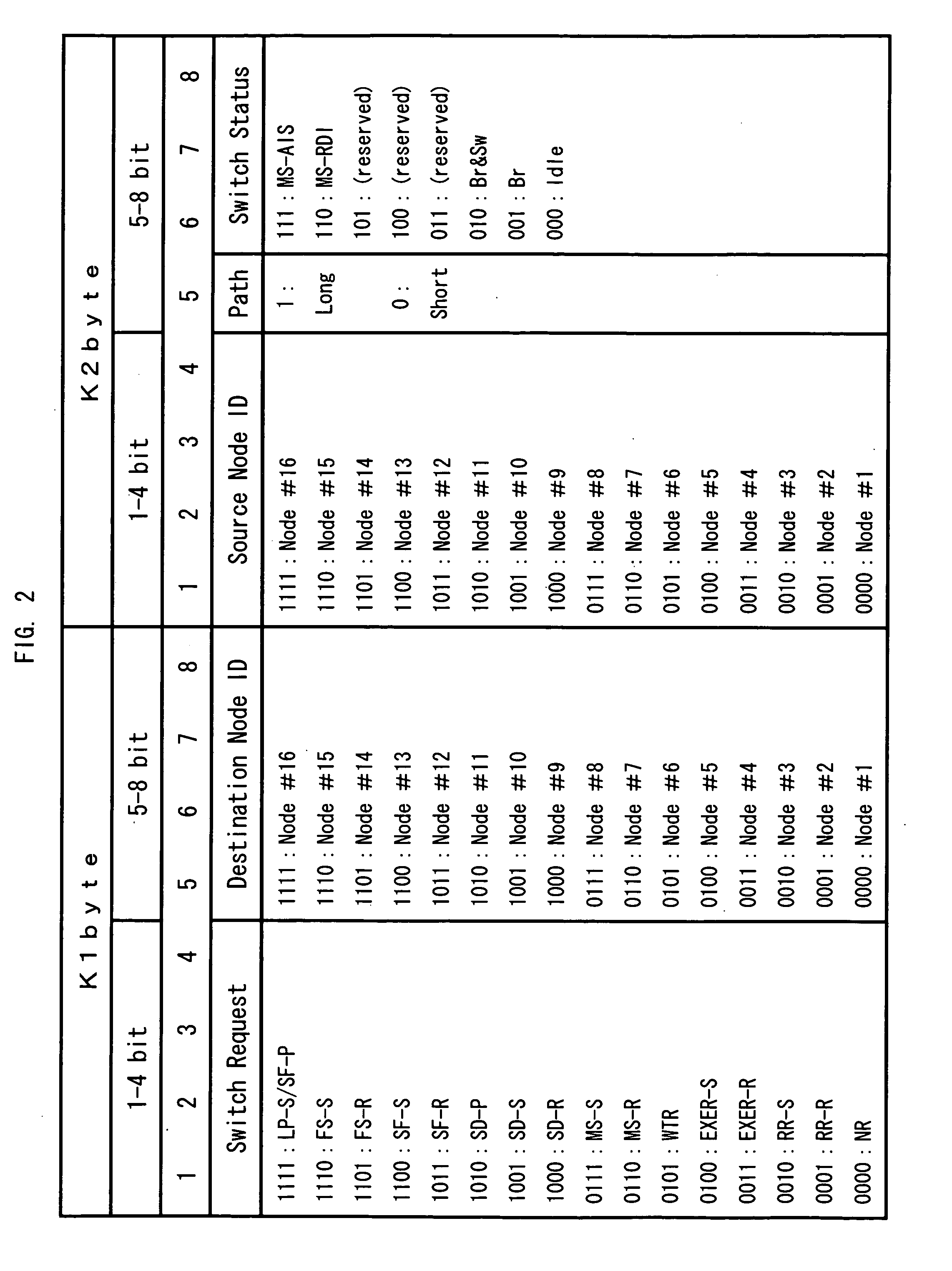
[0061]In the present embodiment based on the configuration illustrated in FIG. 4, a destination node ID and a source node ID that satisfy “destination node ID=source node ID” in K1 and K2 bytes are transmitted, as a protection band control signal, from a node device to an adjacent node device so that a path for checking the communication quality of a protection band can be established. It is also possible to use one of 101, 100, and 011 in the sixth to eighth bits of K2 byte in FIG. 2 as the protection band control signal.


PUM


Abstract

In a ring network system, a first node device includes means for sending out a control signal for controlling one of a plurality of second node devices so as to allow signals transmitted over a protection band to pass through the second node device; each of the second node devices includes means for receiving the control signal sent out from the first node device or another second node device, means for controlling the signals transmitted over the protection band to pass through the second node device during the reception of the control signal, and means for transferring the control signal to the adjacent first node device or to the adjacent second node device during the reception of the control signal; and the first node device further includes means for receiving the control signal transferred from the adjacent second node device.

Description

BACKGROUND OF THE INVENTION[0001]1. Field of the Invention[0002]The present invention relates to a ring network system in which a plurality of node devices are connected in a ring configuration and in which a working band and a protection band combine to form a redundant transmission band pair, to a node device, and to a protection band testing method for the ring network system.[0003]2. Description of the Related Art[0004]A synchronous optical network (SONET) ring is a ring network in which a plurality of SONET / synchronous digital hierarchy transmission (SDH) devices (or SONET devices) with add-drop multiplexer (ADM) capabilities act as node devices. The SONET ring is used in networks, ranging in size from small citywide networks to large nationwide networks. Typical redundancy schemes for the SONET ring include a bi-directional line switched ring (BLSR), which comes in two varieties: a two-fiber BLSR (2F-BLSR) and a four-fiber BLSR (4F-BLSR). In the 2F-BLSR, a transmission band of...

Claims


Application Information

Patent Timeline
IPC IPC(8): H04J1/16H04J3/00H04L12/42H04L12/70
CPCH04J2203/006H04J3/085
Inventor OHKAWA, NAOKATSU
Owner FUJITSU LTD
Features
  • R&D
  • Intellectual Property
  • Life Sciences
  • Materials
  • Tech Scout
  • Unparalleled Data Quality
  • Higher Quality Content
  • 60% Fewer Hallucinations
Learn More