Optical monitor and a method for improved optical monitoring
- Summary
- Abstract
- Description
- Claims
- Application Information
AI Technical Summary
Benefits of technology
Problems solved by technology
Method used
Image
Examples
Embodiment Construction
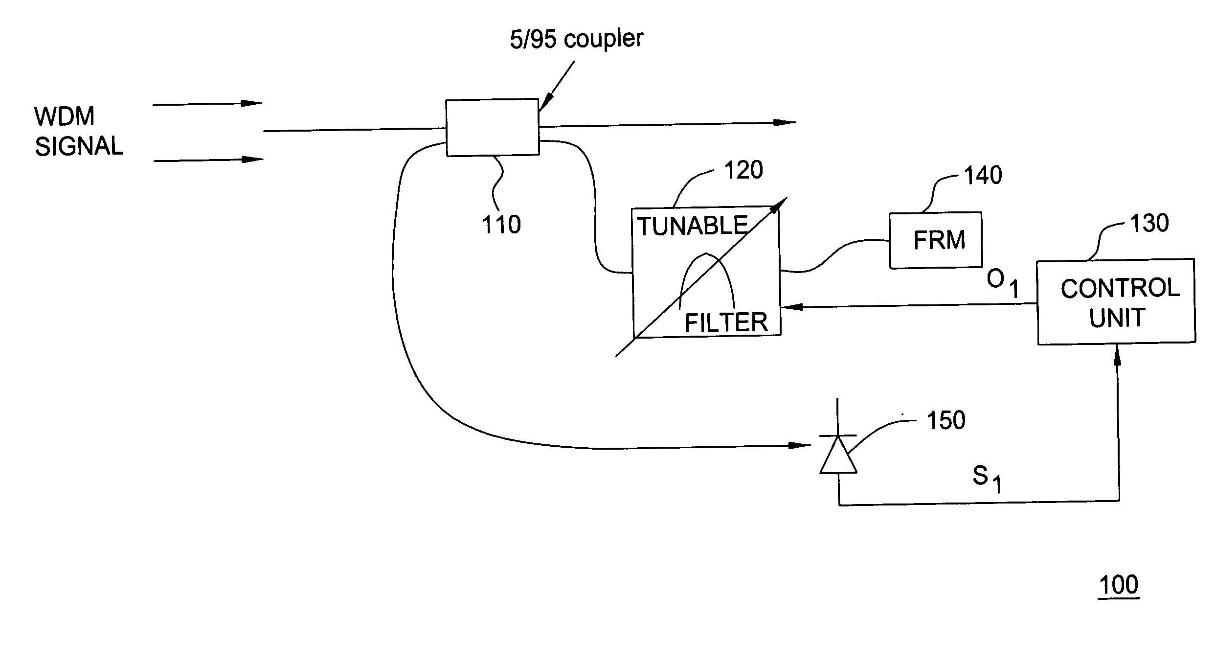
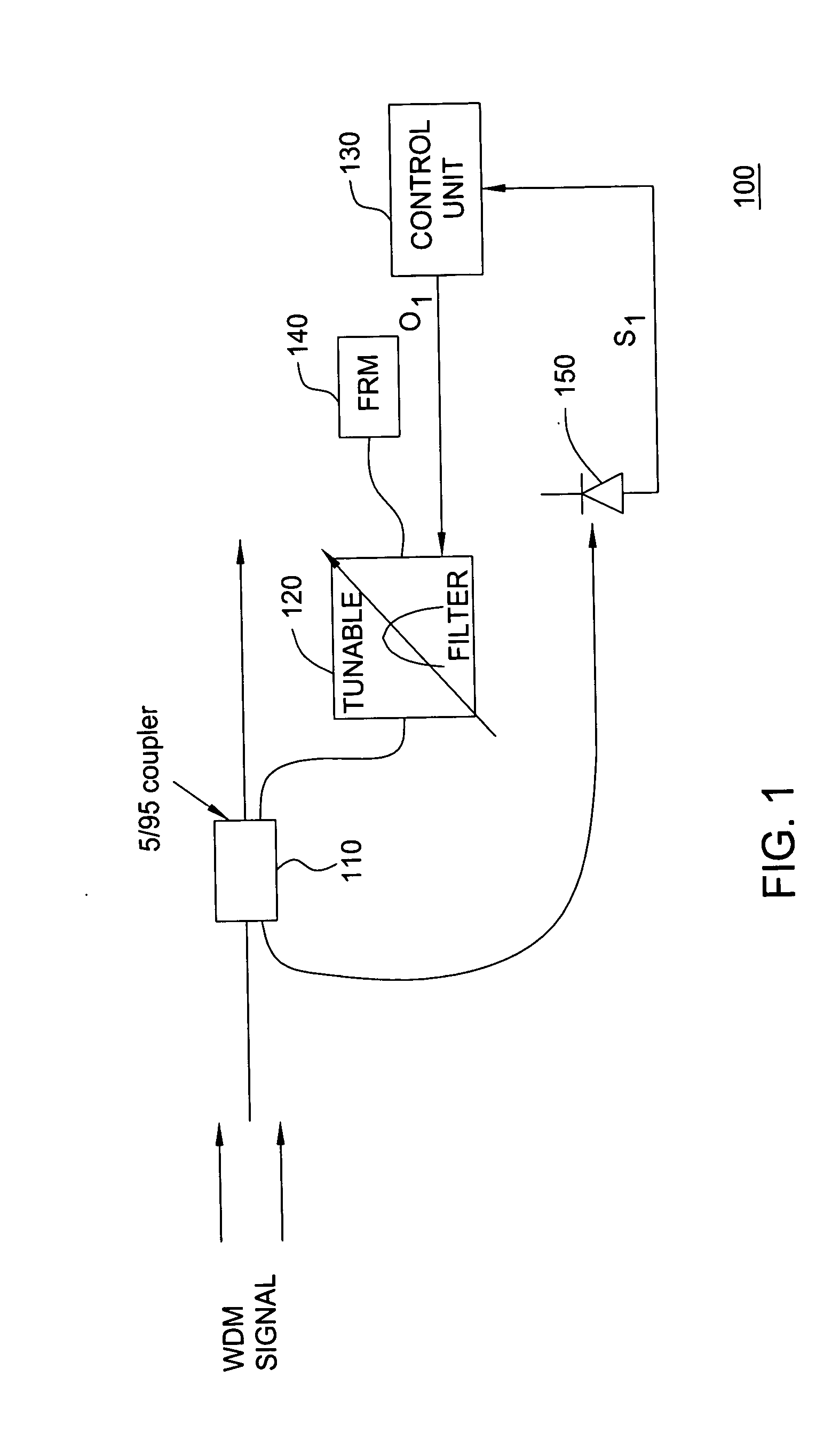
[0016]FIG. 1 depicts a high level block diagram of an embodiment of a novel optical monitor in accordance with the present invention. The optical monitor 100 of FIG. 1 illustratively comprises an optical coupler (illustratively a 5 / 95 optical coupler) 110, a scanning tunable filter 120, a control unit 130, a mirror (illustratively a Faraday rotator mirror (FRM)) 140 and a photodetector 150. Although in FIG. 1, the optical coupler 110 is illustratively depicted as a 5 / 95 optical coupler, optical couplers with various other splitting ratios (e.g., 1 / 99) may also be implemented within an optical monitor in accordance with the present invention. Furthermore, although in FIG. 1, the mirror 140 is illustratively depicted as a Faraday rotator mirror, if the polarization sensitivity of the tunable filter is sufficiently low, the FRM may be replaced by a plain mirror. Furthermore, other means of directing (reflecting) light, such as a Sagnac loop, may be implemented in place of the mirror in...
PUM
 Abstract
Description
Claims
Application Information
 - R&D
- Intellectual Property
- Life Sciences
- Materials
- Tech Scout
- Unparalleled Data Quality
- Higher Quality Content
- 60% Fewer Hallucinations
Browse by: Latest US Patents, China's latest patents, Technical Efficacy Thesaurus, Application Domain, Technology Topic, Popular Technical Reports.
© 2025 PatSnap. All rights reserved.Legal|Privacy policy|Modern Slavery Act Transparency Statement|Sitemap|About US| Contact US: help@patsnap.com


