Composting device

a composting device and composting technology, applied in the field of composters, can solve the problems of inefficiency and time-consuming air barrier, difficult to live for microorganisms, and difficulty in composting by leaving exposed organic matter heaps to decay, etc., and achieve the effect of sufficient ventilation

Inactive Publication Date: 2005-03-10
IDEAS THAT GROW
View PDF7 Cites 7 Cited by
  • Summary
  • Abstract
  • Description
  • Claims
  • Application Information

AI Technical Summary

Benefits of technology

[0009] Advantageously, the composting device of the present invention is an attractive composter for display in a persons yard or garden. The top cover of the composting device together with an ornament mounted thereon, pivots about the remainder of the container and thus, the ornament and the top cover of the composting device together pivot about the remainder of the container. Therefore, the ornament does not need to be removed from the top cover when accessing the charge opening to add compost matter to the container. Instead, the top cover pivots, with the ornament still attached, via a pivot rod to thereby expose the charge opening. Feet on the bottom of the composting device, provide stability as the weight of the top and the ornament are pivoted to expose charge opening. These feet are easily buried under, for example, soil to provide further stability. The double-walled composting device of the present invention includes inner side panels and outer side panels, the inner side panels including openings for ventilation. Insulation from the cold is improved while still providing sufficient ventilation.

Problems solved by technology

Therefore, weather changes such as temperature drops or rain make it difficult for the microorganisms to live.
Thus, composting by leaving heaps of exposed organic matter to decay is inefficient and time-consuming.
Also, conventional composters are unsightly boxes or cylinders and thus it is generally desirable to hide these conventional composters out of sight.
The air barrier, however, consists of captured air and venting of the compost matter is inhibited.
Furthermore, as in the conventional composters, the blow-molded composters are unsightly and are thus generally undesirable or are located in a hidden location in a yard.

Method used


Image

  • Composting device
  • Composting device
  • Composting device

Examples


Embodiment Construction

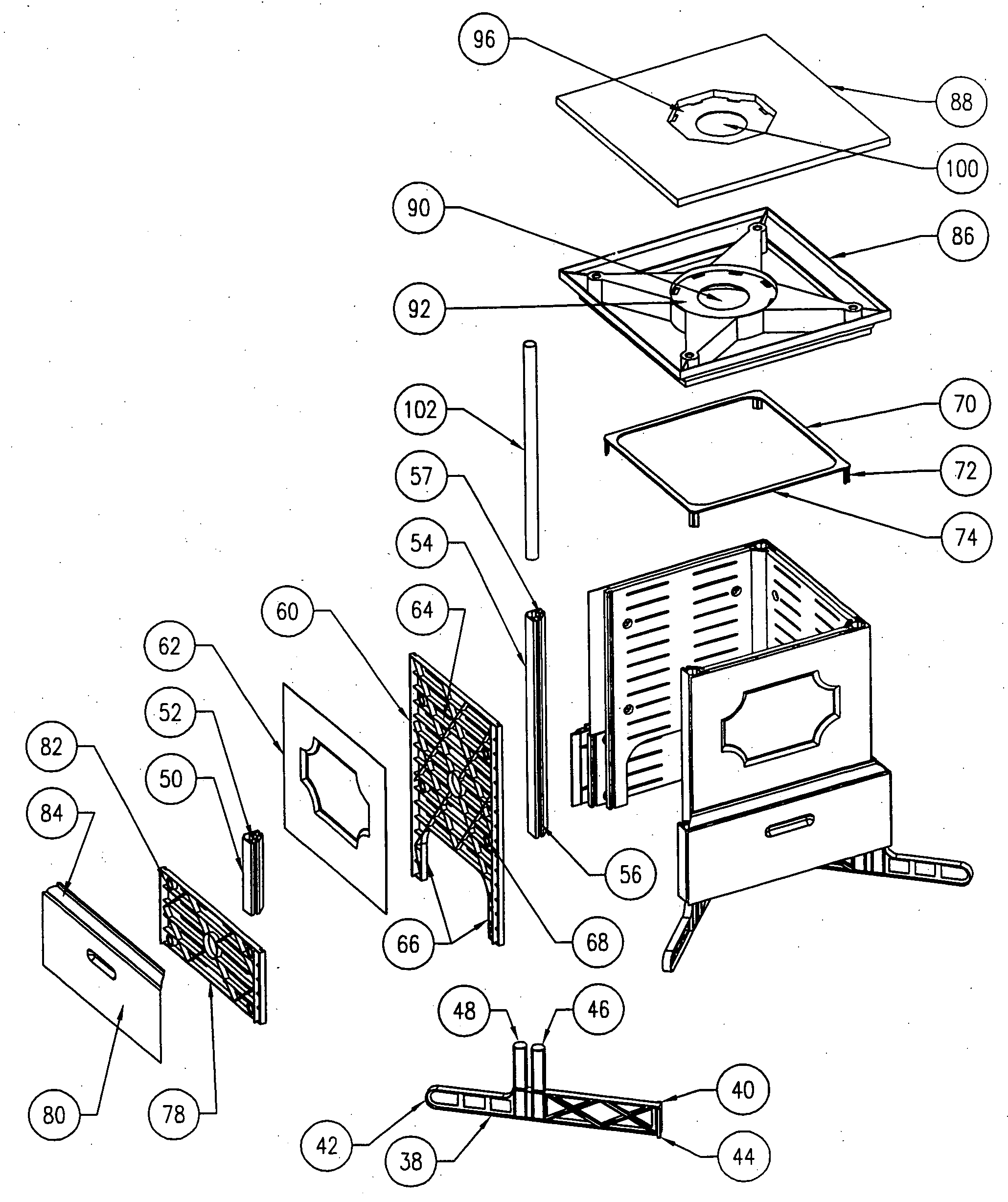
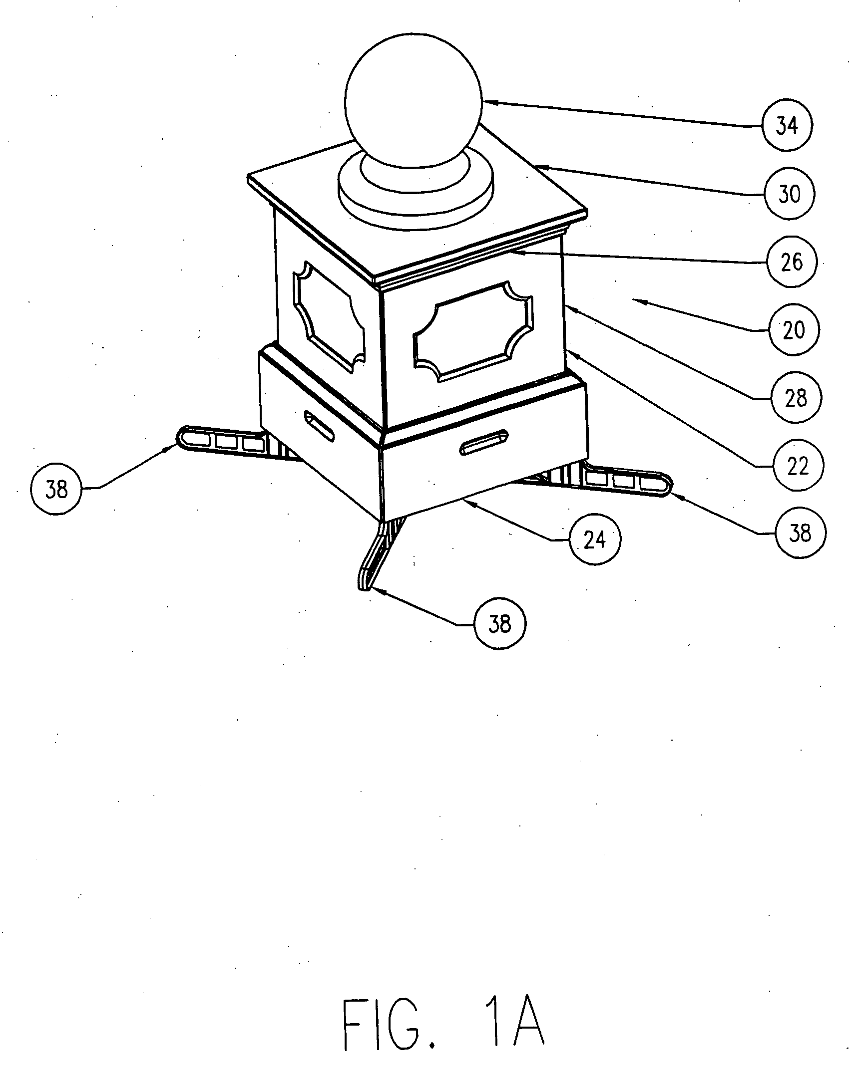
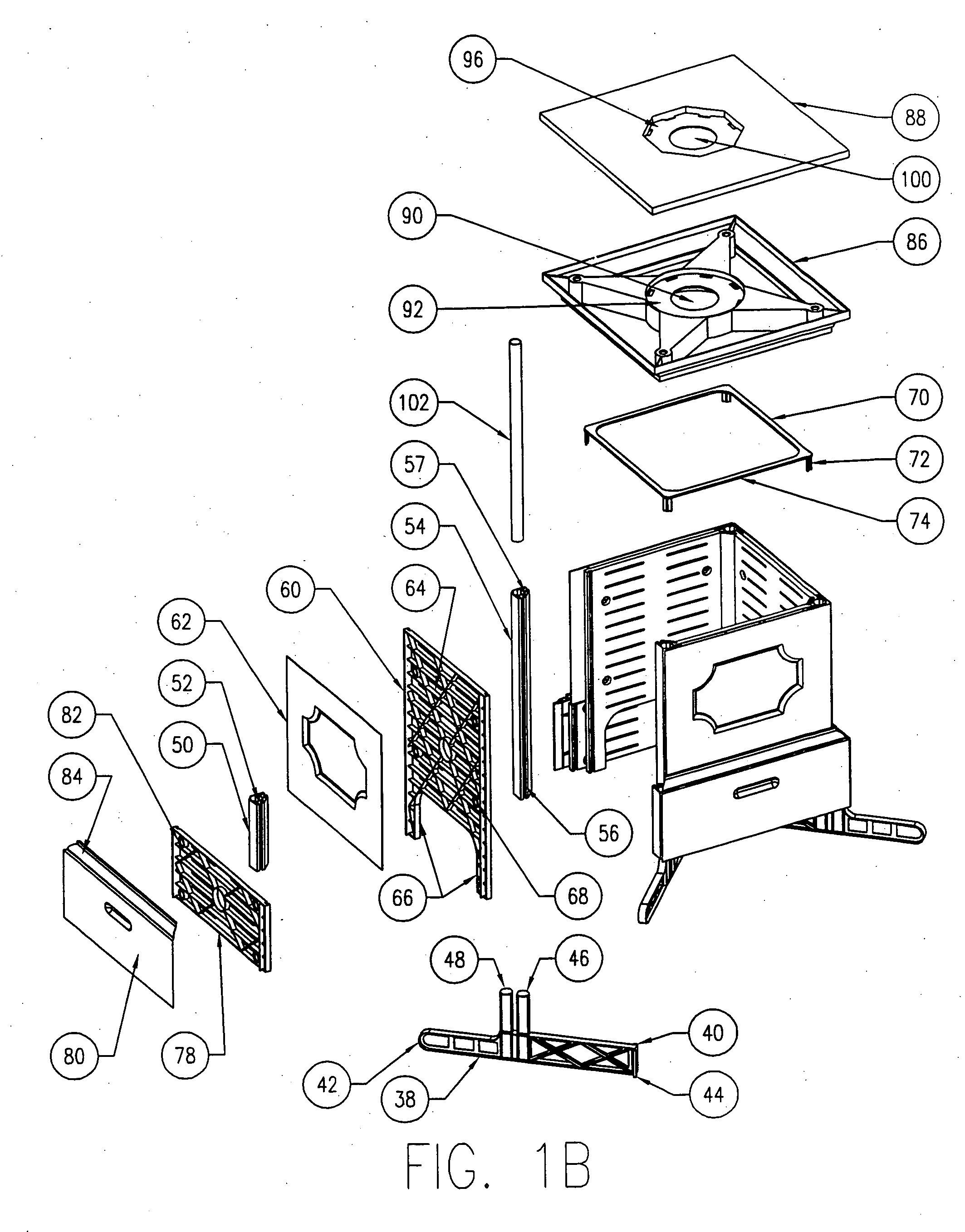
[0020] Reference is first made to FIGS. 1A and 1B to describe an embodiment of the composting device designated generally by the numeral 20. The composting device 20 includes a hollow container 22 having an open bottom end 24, a top end 26 and at least one sidewall 28 extending therebetween. The top end 26 includes a charge opening therein for adding organic matter. The container 22 also includes a discharge opening proximal the bottom end 24 for removing compost matter. A removable top cover 30 for cooperating with the top end 26 of the hollow container 22, covers the charge opening. The top cover 30 is removable to expose the charge opening and includes a connector portion. An ornament 34 includes a corresponding complementary connector portion, the complementary connector portion cooperating with the connector portion of the top cover 30, for mounting the ornament 34 thereon.

[0021] The composting device 20 and assembly thereof will now be described in more detail, with reference...


PUM

PropertyMeasurementUnit
densityaaaaaaaaaa
temperatureaaaaaaaaaa
timeaaaaaaaaaa

Abstract

A composting device for composting organic matter, includes a hollow container having a bottom end, a top end and at least one sidewall extending therebetween. The top end includes a charge opening therein for adding organic matter. The container also includes a discharge opening for proximal the bottom end for removing compost matter. A removable top cover for cooperating with the top end of the hollow container, covers the charge opening. The top cover is removable to expose the charge opening and includes connection means. An ornament including a corresponding complementary connection means, the complementary connection means cooperating with the connection means of the top cover, for mounting the ornament on the top cover.

Description

FIELD OF THE INVENTION [0001] This invention relates to composters. More particularly, this invention relates to an improved composter with unique architecture facilitating the addition and venting of compost matter. BACKGROUND OF THE INVENTION [0002] Composting is a well-known process in which organic matter is converted into humus by microorganisms that consume the organic matter. These microorganisms are aerobic, requiring oxygen to live, and thrive in warm environments. When compost matter becomes wet, the density of the compost matter increases and ventilation is reduced. Therefore, weather changes such as temperature drops or rain make it difficult for the microorganisms to live. Thus, composting by leaving heaps of exposed organic matter to decay is inefficient and time-consuming. Composters have been designed to protect the compost matter and prolong the life of the microorganisms, thereby providing more efficient breakdown of the organic matter. [0003] Conventional composte...

Claims


Application Information

Patent Timeline
Patent Type & Authority Applications(United States)
IPC IPC(8): C05F9/02C05F17/02C12M1/00
CPCY10S220/908C05F17/0205Y02P20/145C05F17/907Y02W30/40
Inventor NAGY, JAYNERAYBURN, KATHYRAYBURN, JAMES KIRBYMORAWIETZ, RICHARD PAUL
Owner IDEAS THAT GROW
Why Eureka
Try Eureka