Window evaporative cooler

a technology of evaporative cooler and window, which is applied in the field of installing a low-profile evaporative cooler, can solve the problems of blocking the window from being used by the cooler, affecting the maintenance of the roof-mounted cooler, and many roof-mounted coolers being banned

Inactive Publication Date: 2005-03-10
ADOBEAIR INC
View PDF39 Cites 33 Cited by
  • Summary
  • Abstract
  • Description
  • Claims
  • Application Information

AI Technical Summary

Benefits of technology

[0008] Another embodiment of the invention relates to a method for installing an evaporative cooler in a window located in a building. The window includes at least one movable portion. An evaporative cooler is provided that includes a housing with a vertical height extending from the ground lower than the vertical height of the bottom of the window. A first portion of a duct is attached to the housing. A frame is placed between the movable portion of the window and the building. A second portion of the duct is secured to the frame; and operatively secured to the frame between the movable portion of the window and the building.

Problems solved by technology

However, maintenance of the roof-mounted coolers is difficult due to access.
Additionally, many roof mounted coolers are being banned under local zoning ordinances due to the aesthetic nature of the cooler located on the roof.
This approach has a number of disadvantages including blocking the window from use by the cooler.
Additionally, some local zoning ordinances require do not permit evaporative coolers that extend over the top of the fence line.

Method used


Image

  • Window evaporative cooler
  • Window evaporative cooler
  • Window evaporative cooler

Examples


Embodiment Construction

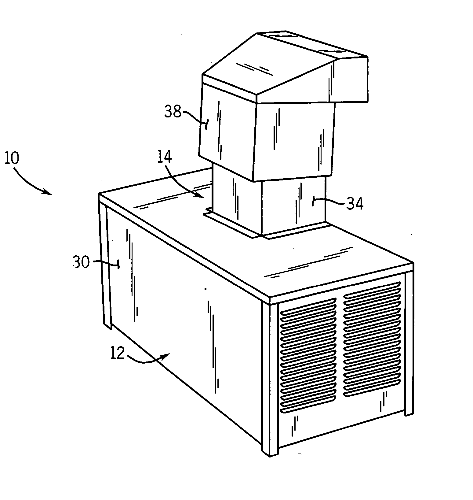
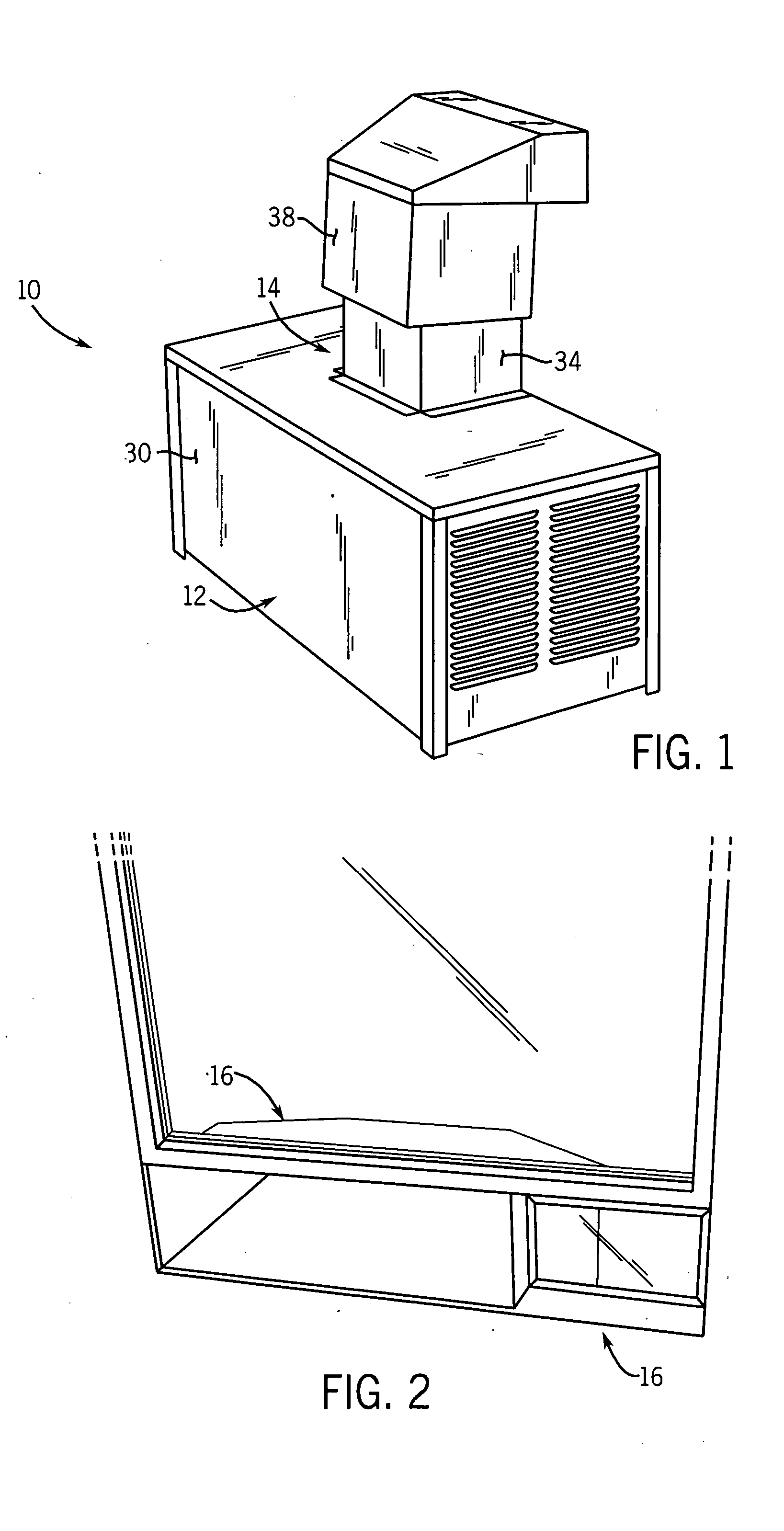
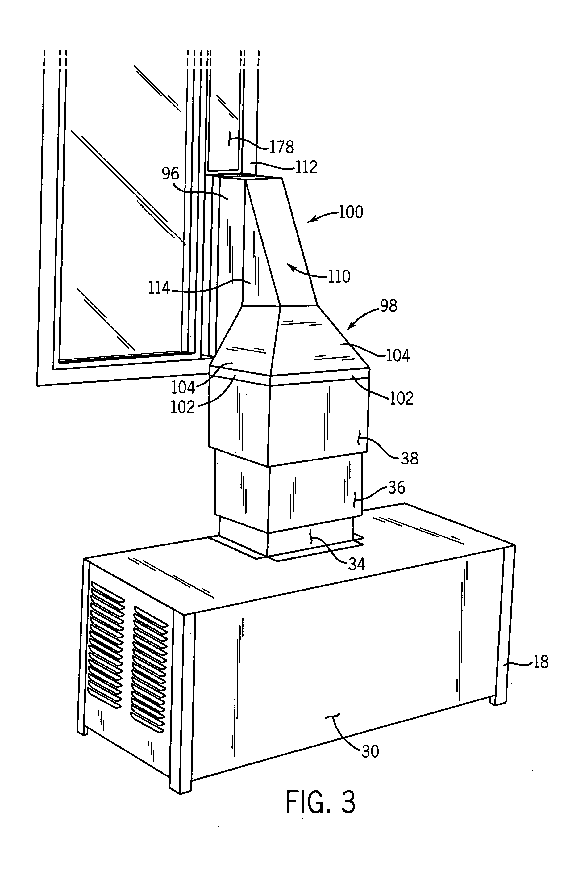
[0022] Referring to FIGS. 1-3, a window evaporative cooler 10 includes a housing 12, a telescoping duct system 14 and a grill system 16. Housing 12 may be located directly on the ground, or may be supported on feet 18 or any standard support to ensure that the housing is in a horizontal position. Housing 12 stores a pump (not shown) for pumping water through a flexible or rigid media (not shown). A fan 19 draws outside air into housing 12, through the wetted media and is blown upward through an opening 22 in a top panel 24 of housing 12.

[0023] Referring to FIG. 4, extending upward from top panel 24 of housing 12 and surrounding opening 22 are flanges 26. Opening 22 is located proximate the rear panel or side 28 of housing 12. For description purposes, the rear panel of housing 12 is the portion that is adjacent or facing the outside of the building. Accordingly, front side 30 of housing is the panel. A screen 32 is located adjacent opening 22 between flanges 26 and rear panel 28.

[...


PUM


Abstract

A method for installing an evaporative cooler in a window located in a building includes placing an evaporative cooler housing below the bottom of the window. A duct is attached to the housing and extended upward to the window. A frame is placed between the movable portion of the window and the building. The second portion of the duct is secured to the frame and the frame is operatively secured between a movable portion of the window and the building. An evaporative cooler, adjustable duct assembly, diverter and frame assembly are also disclosed.

Description

BACKGROUND OF THE INVENTION [0001] The present invention relates generally to the field of evaporative coolers, and more particularly to a method and apparatus for installing a low profile evaporative cooler that does not significantly block the window view. [0002] Evaporative coolers are well know and used in warm dry climates to both raise the humidity and cool the air. Evaporative coolers work by drawing air from outside through a media soaked with water. As the air flows through the soaked media water is evaporated by the outside air thereby lowering the temperature of the air. The cooled air is then directed into the area to be cooled. [0003] An evaporative cooler includes a number of elements all of which are stored in a housing. These elements typically include an air blower; a media pad; a water distribution system; and an electric motor. Evaporative coolers need to be maintained on a periodic basis to replace the media pads and to clean the water distribution system. [0004]...

Claims


Application Information

Patent Timeline
Patent Type & Authority Applications(United States)
IPC IPC(8): F24F5/00F24F13/20
CPCF24F5/0035Y02B30/545F24F13/20Y02B30/54
Inventor GREEN, JACE N.PALMER, ROGER C.
Owner ADOBEAIR INC
Why Eureka
Try Eureka