Method of chilling inlet air for gas turbines

US20050056023A1Inactive Publication Date: 2005-03-17TAS ENERGY +1

Image

  • Method of chilling inlet air for gas turbines
  • Method of chilling inlet air for gas turbines
  • Method of chilling inlet air for gas turbines

Examples


Embodiment Construction

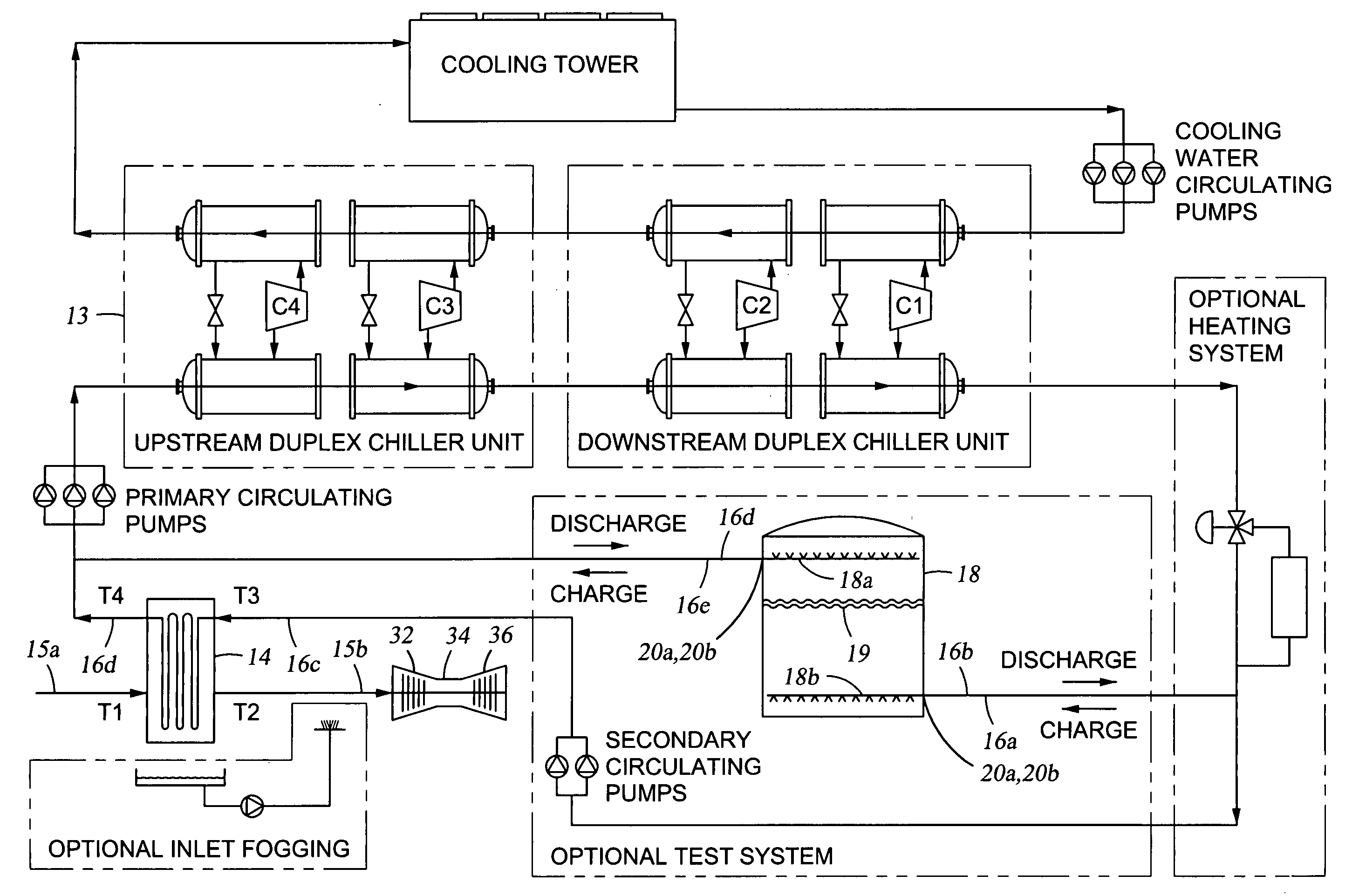
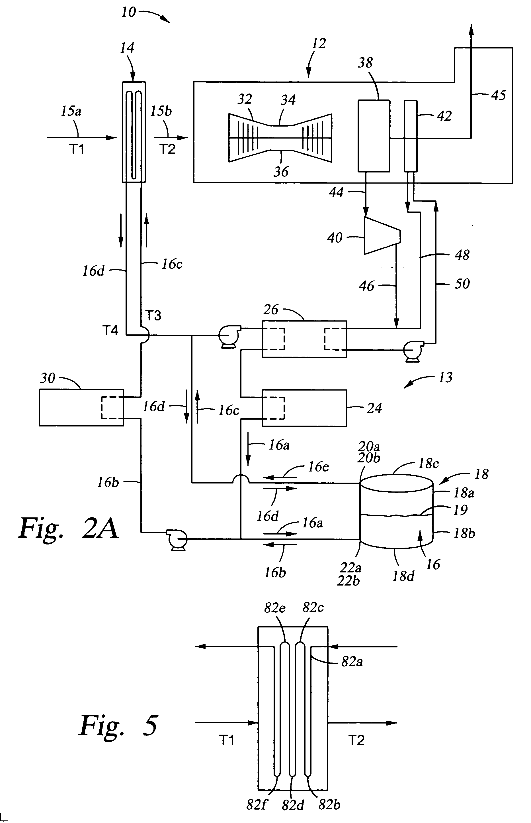
Specific embodiments of the invention will now be described. However, a person of ordinary skill in the art will recognize that the invention will actually be defined by one or more of the claims, rather than the description below. Depending on the context, all references to the “invention” below may in some cases refer to certain specific embodiments only. In other cases it will be recognized that references to the “invention” will refer to subject matter recited in one or more, but not necessarily all, of the claims.

A. Inlet Air Cooling

Generally, referring to FIG. 1, the overall apparatus 10 includes a conventional gas turbine system 12 having an air chiller 14, e.g., a conventional cooling coil, for lowering the temperature of inlet air, shown schematically by arrow 15a, from ambient temperature (T1, e.g., about 90° F. (about 32° C.), or in the range of from about 70° F. (about 21° C.) to about 85° F. (about 29° C.) to a range of from about 100° F. (about 38°C.) to about 115...


PUM


Abstract

A method for cooling inlet air to a gas turbine is provided. For example, a method is described including passing inlet air through a cooling coil that includes an opening for receiving the inlet air and that is operably connected to a gas turbine power plant. The gas turbine power plant may include at least one gas turbine, and at least one gas turbine inlet which receives the inlet air. The method may further include passing circulating water through a water chiller at a first flow rate to reduce the temperature of the circulating water, the water chiller including a conduit through which the circulating water is capable of passing and passing the circulating water having the first flow rate through the cooling coil in an amount sufficient to lower the temperature of the inlet air. Additionally, the method may include reducing the flow rate of the circulating water passing through the water chiller, passing the circulating water through a water chiller at a second flow rate to reduce the temperature of the circulating water, the second flow rate being lower than the first flow rate, and passing the circulating water having the second flow rate through the cooling coil in an amount sufficient to lower the temperature of the inlet air.

Description

BACKGROUND OF INVENTION 1. Field of the Invention This invention relates broadly to cooling inlet air to a gas turbine. 2. Description of Related Art. A conventional gas turbine system includes: an air compressor for compressing the turbine inlet air; a combustion chamber for mixing the compressed air with fuel and combusting the mixture, thereby producing a combustion gas; and a power turbine that is driven by the combustion gas, thereby producing an exhaust gas and useful power. Over the years, various technologies have been employed to increase the amount of useful power that the power turbine is able to produce. One way of increasing the power output of a gas turbine is to cool the turbine inlet air prior to compressing it in the compressor. Cooling causes the air to have a higher density, thereby creating a higher mass flow rate through the turbine. The higher the mass flow rate through the turbine, the more power the turbine produces. Cooling the turbine inlet air tempera...

Claims


Application Information

Patent Timeline
17 Mar 2005
Publication
US20050056023A1
IPC
F01K23/10; F02C7/143; F24F3/06; F24F5/00; F25B27/02
CPC
F01K23/10; F02C7/143; F24F3/06; F24F5/0017; Y02E60/147; F25B2339/047; F25B2400/06; Y02E20/16
Inventors
PIERSON, TOM L.