Method of chilling inlet air for gas turbines

a gas turbine and inlet air technology, which is applied in the direction of machines/engines, lighting and heating apparatus, heating types, etc., can solve the problems of surplus power from the turbine and system is limited to cooling the air to the wet bulb temperature, and achieve the effect of lowering the average temperature of the chilling water and lowering the temperature of the inlet air

Inactive Publication Date: 2008-03-18
TAS ENERGY +1
View PDF39 Cites 61 Cited by
  • Summary
  • Abstract
  • Description
  • Claims
  • Application Information

AI Technical Summary

Benefits of technology

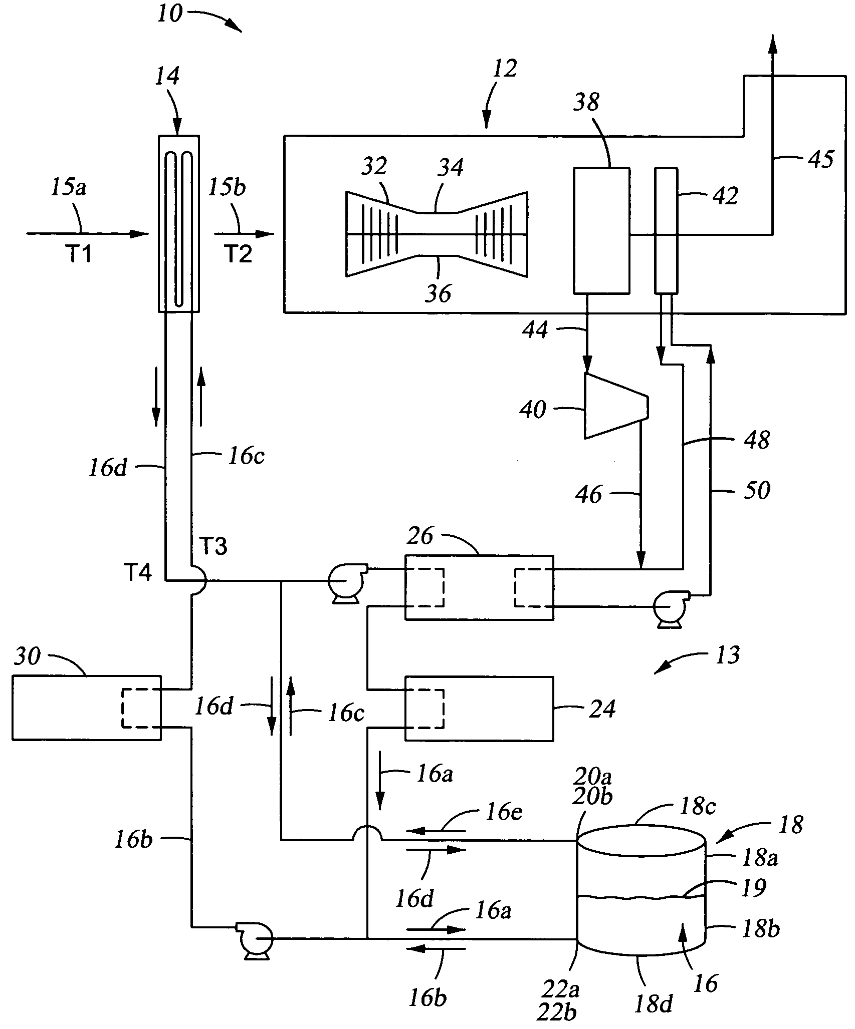
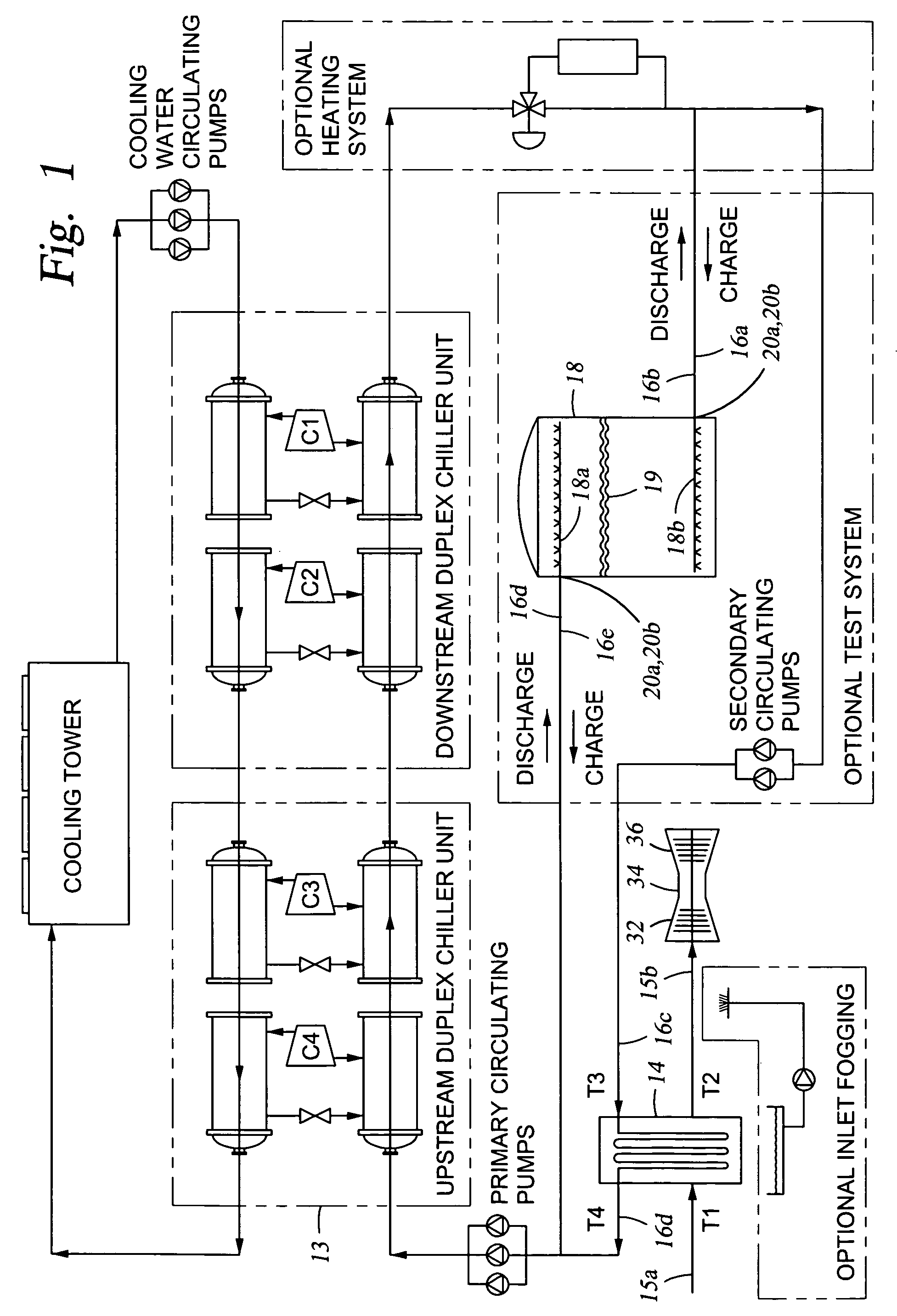
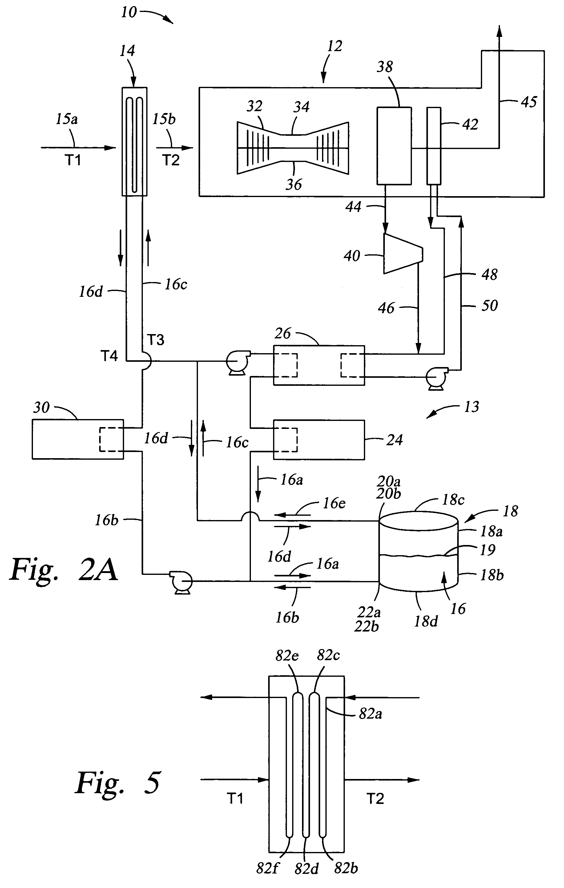
[0008]Described in greater detail below is a method for chilling inlet air to a gas turbine power plant, which may include: providing a system of circulating chilling water including a chilling system; providing an inlet air chiller for lowering the temperature of the inlet air being fed to a gas turbine compressor through heat transfer between the circulating chilling water and the inlet air, providing a thermal water storage tank which is operably connected to the system of circulating chilling water, the thermal water storage tank containing chilling water having a bottom; during a charge cycle, removing a first portion of chilling water from the thermal water storage tank, passing the removed first portion of water through the chilling system to lower the temperature of the removed first portion of water and to provide a chilled removed first portion of water, and then introducing the chilled removed first portion of water into the thermal water storage tank at a point proximate the bottom of the tank, wherein the chilled removed first portion of water is introduced to the tank in an amount sufficient to lower the average temperature of the chilling water in the thermal water storage tank; and during a discharge cycle, chilling the inlet air by removing a second portion of chilling water from the thermal water storage tank, from a point proximate the bottom of the tank and then passing the second portion of chilling water to the inlet air chiller to make heat transfer contact between the second portion of chilling water and the inlet air, such that the temperature of the inlet air is lowered.

Problems solved by technology

This system is limited to cooling the air to the wet bulb temperature, which is dependent upon the atmospheric conditions at any given time.
This system requires parasitic power or steam to drive the chilling system which has the further drawback that when inlet air cooling is needed the most, i.e. during the day when the temperature is the highest, is also the time when power demand from the turbine is the highest, i.e. during the day when power users are in operation.
On the other hand, when cooling is needed the least, i.e. at night when the temperatures are the lowest, surplus power from the turbine is available because the consumers of the turbine's power are largely not in operation.

Method used


Image

  • Method of chilling inlet air for gas turbines
  • Method of chilling inlet air for gas turbines
  • Method of chilling inlet air for gas turbines

Examples


Embodiment Construction

[0036]Specific embodiments of the invention will now be described. However, a person of ordinary skill in the art will recognize that the invention will actually be defined by one or more of the claims, rather than the description below. Depending on the context, all references to the “invention” below may in some cases refer to certain specific embodiments only. In other cases it will be recognized that references to the “invention” will refer to subject matter recited in one or more, but not necessarily all, of the claims.

A. Inlet Air Cooling

[0037]Generally, referring to FIG. 1, the overall apparatus 10 includes a conventional gas turbine system 12 having an air chiller 14, e.g., a conventional cooling coil, for lowering the temperature of inlet air, shown schematically by arrow 15a, from ambient temperature (T1, e.g., about 90° F. (about 32° C.), or in the range of from about 70° F. (about 21° C.) to about 85° F. (about 29° C.) to a range of from about 100° F. (about 38° C.) to a...


PUM


Abstract

A method for cooling inlet air to a gas turbine is provided. For example, a method is described including passing inlet air through a cooling coil that includes an opening for receiving the inlet air and that is operably connected to a gas turbine power plant. The gas turbine power plant may include at least one gas turbine, and at least one gas turbine inlet which receives the inlet air. The method may further include passing circulating water through a water chiller at a first flow rate to reduce the temperature of the circulating water, the water chiller including a conduit through which the circulating water is capable of passing and passing the circulating water having the first flow rate through the cooling coil in an amount sufficient to lower the temperature of the inlet air. Additionally, the method may include reducing the flow rate of the circulating water passing through the water chiller, passing the circulating water through a water chiller at a second flow rate to reduce the temperature of the circulating water, the second flow rate being lower than the first flow rate, and passing the circulating water having the second flow rate through the cooling coil in an amount sufficient to lower the temperature of the inlet air.

Description

CROSS-REFERENCE TO RELATED APPLICATIONS[0001]This application is a continuation of U.S. patent application Ser. No. 10 / 206,856, filed Jul. 26, 2002, now U.S. Pat. No. 6,769,528 which is a continuation-in-part of U.S. patent application Ser. No. 09 / 961,711, filed Sep. 24, 2001, now U.S. Pat. No. 6,470,686, which is a continuation of U.S. patent application Ser. No. 09 / 369,788, filed Aug. 6, 1999, now U.S. Pat. No. 6,318,065.BACKGROUND OF INVENTION[0002]1. Field of the Invention[0003]This invention relates broadly to cooling inlet air to a gas turbine.[0004]2. Description of Related Art.[0005]A conventional gas turbine system includes: an air compressor for compressing the turbine inlet air; a combustion chamber for mixing the compressed air with fuel and combusting the mixture, thereby producing a combustion gas; and a power turbine that is driven by the combustion gas, thereby producing an exhaust gas and useful power.[0006]Over the years, various technologies have been employed to ...

Claims


Application Information

Patent Timeline
Patent Type & Authority Patents(United States)
IPC IPC(8): F02C1/00F01K23/10F02C7/143F24F3/06F24F5/00F25B27/02
CPCF01K23/10F02C7/143F24F3/06F24F5/0017F25B27/02F25B2339/047F25B2400/06Y02E20/16Y02E60/147Y02A30/274Y02E60/14
Inventor PIERSON, TOM L.
Owner TAS ENERGY
Why Eureka
Try Eureka