Processes and Device for Low Temperature Separation of Air

a technology of low temperature separation and process, which is applied in the direction of refrigeration and liquid storage, lighting and heating equipment, solidification, etc., can solve the problems of turbine damage, inability to unconditionally lower the temperature at the turbine inlet, etc., and achieve the effect of low equipment cos

Inactive Publication Date: 2011-03-24
LINDE AG
View PDF9 Cites 4 Cited by
  • Summary
  • Abstract
  • Description
  • Claims
  • Application Information

AI Technical Summary

Benefits of technology

[0008]The present invention is based on the problem of achieving an energy-efficient process and a corresponding device, with a comparatively low equipment cost.
[0011]In a first variant of the present invention, a recompressor operates on external power; both the throttling stream and the turbine stream are under the second pressure during cooldown in the main heat exchanger. Using a recompressor without intermediate offtake, the equipment cost can be kept low.
[0018]In a modification of the first variant, the present invention comprises at least two stages instead of the recompressor and can also be driven with external power. The further compression at the second pressure then occurs in at least a first stage of the recompressor; the throttling stream is further compressed downstream of the branching off of the turbine stream at least in the last stage of the recompressor at a third pressure, which is higher than the second pressure. The steps according to the invention of cooldown, expansion, and heat-up of the turbine stream create so much additional flexibility that the process can attain a high efficiency, even if the construction-dependent intermediate offtake pressures of the recompressors are in themselves unfavorable.
[0019]Preferably, the intermediate pressure is 1.5 to 5 bars below the second pressure, that is, the turbine stream in front of the inlet into the expansion machine is expanded by this pressure difference. This relatively low throttling at the low temperature causes practically no power loss and still allows the desired reduction in the inlet temperature of the expansion machine.

Problems solved by technology

Lowering the temperature at the turbine inlet is however not unconditionally possible but, with the machines generally used, a maximum liquid fraction of roughly 6% to a maximum of 10% (design criterion) is provided.
Higher liquid fractions can lead to turbine damage.

Method used


Image

  • Processes and Device for Low Temperature Separation of Air
  • Processes and Device for Low Temperature Separation of Air
  • Processes and Device for Low Temperature Separation of Air

Examples


Embodiment Construction

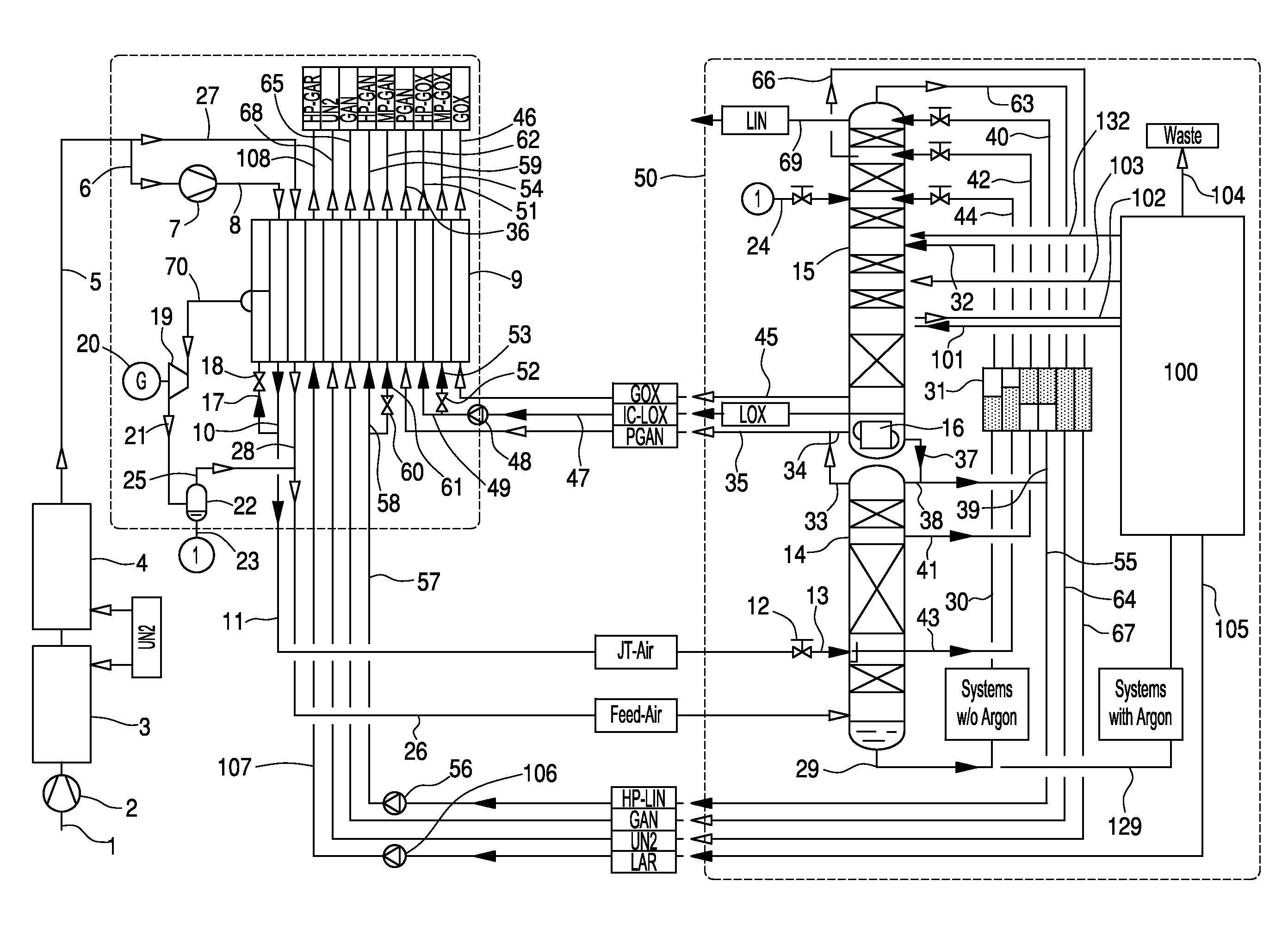
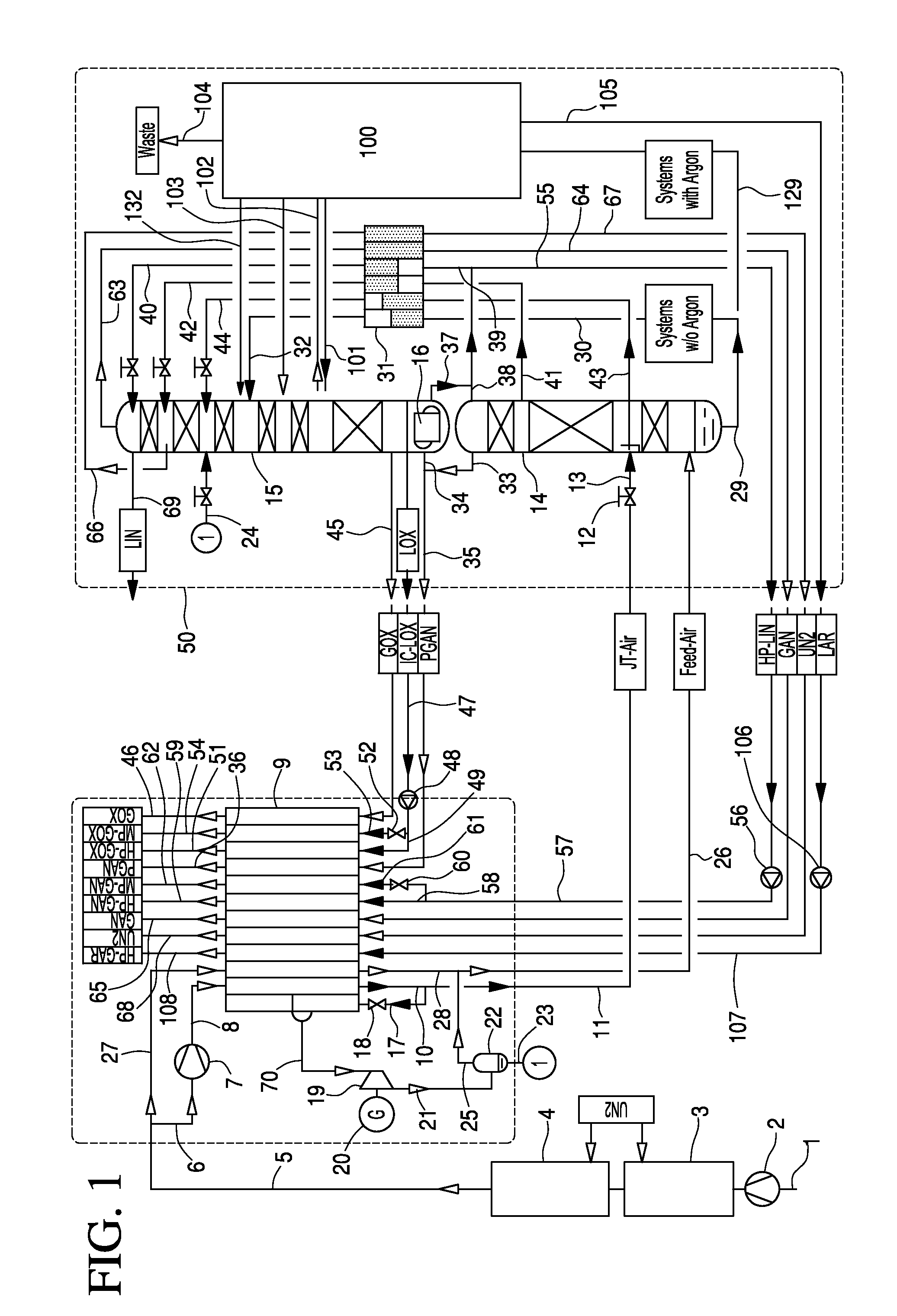
[0030]In the embodiment of FIG. 1, the distillation-column system 50 comprises, in the part which serves for the nitrogen-oxygen separation, a high-pressure column 14, a low-pressure column 15, and a main condenser 16 constructed as a condenser-evaporator, at which the two columns stand relative to heat exchange.

[0031]Atmospheric air is sucked in as main air stream 1 to an air compressor 2, and is brought there to a first pressure that corresponds roughly to the operating pressure of the high-pressure column 14, is cooled down in a primary cooling 3 to roughly ambient temperature, and is conducted to an adsorptive air purification 4. A first portion of the purified main air stream 5 is further compressed as a “first air stream”6 in a recompressor 7 at a second pressure of at least 50 bars, for example roughly 60 bars. The high-pressure air 8 is conducted to the hot end of a main heat exchanger 9 and is cooled down and pseudo-liquefied in the main heat exchanger. The pseudo-liquefied...


PUM


Abstract

The process and device serve for the low-temperature separation of air in a distillation-column system includes at least one separation column. A main air stream is compressed in an air compressor at a first pressure and is then purified. A first air stream, which is formed from at least one part of the purified main air stream, is further compressed at a second pressure that is higher than the first pressure. From the further compressed first air stream, a throttling stream and a turbine stream are branched off. The throttling stream is cooled down and liquefied or pseudo-liquefied in a main heat exchanger and is then passed on to expansion equipment. The expanded throttling stream is conducted into the distillation-column system. The turbine stream is cooled down in the main heat exchanger and under an intermediate temperature of the main heat exchanger is conducted into an expansion machine.

Description

[0001]This U.S. patent application claims priority of German patent document DE 10 2009 042410.5 filed on Sep. 21, 2009 and German patent document DE 10 2009 0484156.6 filed on Oct. 7, 2009, the entireties of which are incorporated herein by reference.FIELD OF INVENTION[0002]The invention is directed to a method and device for the low temperature separation of air with a distillation-column system.BACKGROUND OF INVENTION[0003]A process in which a product flow of liquid at pressure is vaporized against a heat carrier and is finally obtained as a gaseous compressed product is also called an internal compression process. The process is particularly widespread for obtaining compressed oxygen, but can also be used to obtain compressed nitrogen or compressed argon. For the case of a supercritical pressure in a main heat exchanger, no phase transformation occurs in a real sense; the product stream is then “pseudo-vaporized”.[0004]Compared to the (pseudo-)vaporized product stream, a heat ca...

Claims


Application Information

Patent Timeline
Patent Type & Authority Applications(United States)
IPC IPC(8): F25J3/04
CPCF25J3/04054F25J2270/02F25J3/0409F25J3/04096F25J3/04175F25J3/04296F25J3/04303F25J3/04309F25J3/04315F25J3/04393F25J3/04412F25J3/04648F25J2205/04F25J2215/54F25J2240/04F25J2240/42F25J2240/44F25J2240/46F25J3/04084F25J3/04781F25J3/04375F25J2240/10F25J3/04666
Inventor ALEKSEEV, ALEXANDER
Owner LINDE AG
Why Eureka
Try Eureka