
Rotary valve assembly

a valve assembly and rotary valve technology, applied in mechanical equipment, transportation and packaging, separation processes, etc., can solve the problems of cigar storage outside the generally accepted limits, complex and expensive process fluid control, and limited use of assembly for fluid flow applications, so as to avoid the detrimental effects of instantaneous pressure changes on system and component performance, and be more flexible.

Inactive Publication Date: 2007-10-25
MICHAELS GREGORY A
View PDF11 Cites 23 Cited by
  • Summary
  • Abstract
  • Description
  • Claims
  • Application Information

AI Technical Summary

Benefits of technology

[0012]The novel rotary valve assembly described herein provides a means to optimize a process, decrease complexity of design and increase efficiency of a system. Such advantageous effects provide opportunity to lower capital equipment cost.

Problems solved by technology

Previous valve assemblies are of limited use for fluid flow applications because of their lack of flow-control adaptability, reversal or metering.
This need for multiple valves and control circuitry to coordinate the operation of the many valves made process fluid control complex and expensive.
Cigar storage outside these generally accepted limits may be detrimental to flavour, draw, burn and other favourable characteristics.
Relative humidity lower than a set point results in evaporation of water and increase in humidity within the humidor.
One limitation to such a humidifier system is an inability to remove excess moisture.
If the relative humidity within a humidor is greater than desired, humidifier only systems provide no relief.
Passive humidity control systems do not provide circulation within a humidor and use physical-chemical properties of materials, e.g., propylene glycol solutions, silica gel, salts and other compounds to regulate relative humidity in stagnant air.
Thus, both active and passive systems have significant shortcomings, and systems employing a multitude of conventional valves is impractical due to cost and complexity.

Method used


Image

  • Rotary valve assembly
  • Rotary valve assembly
  • Rotary valve assembly

Examples


example 1

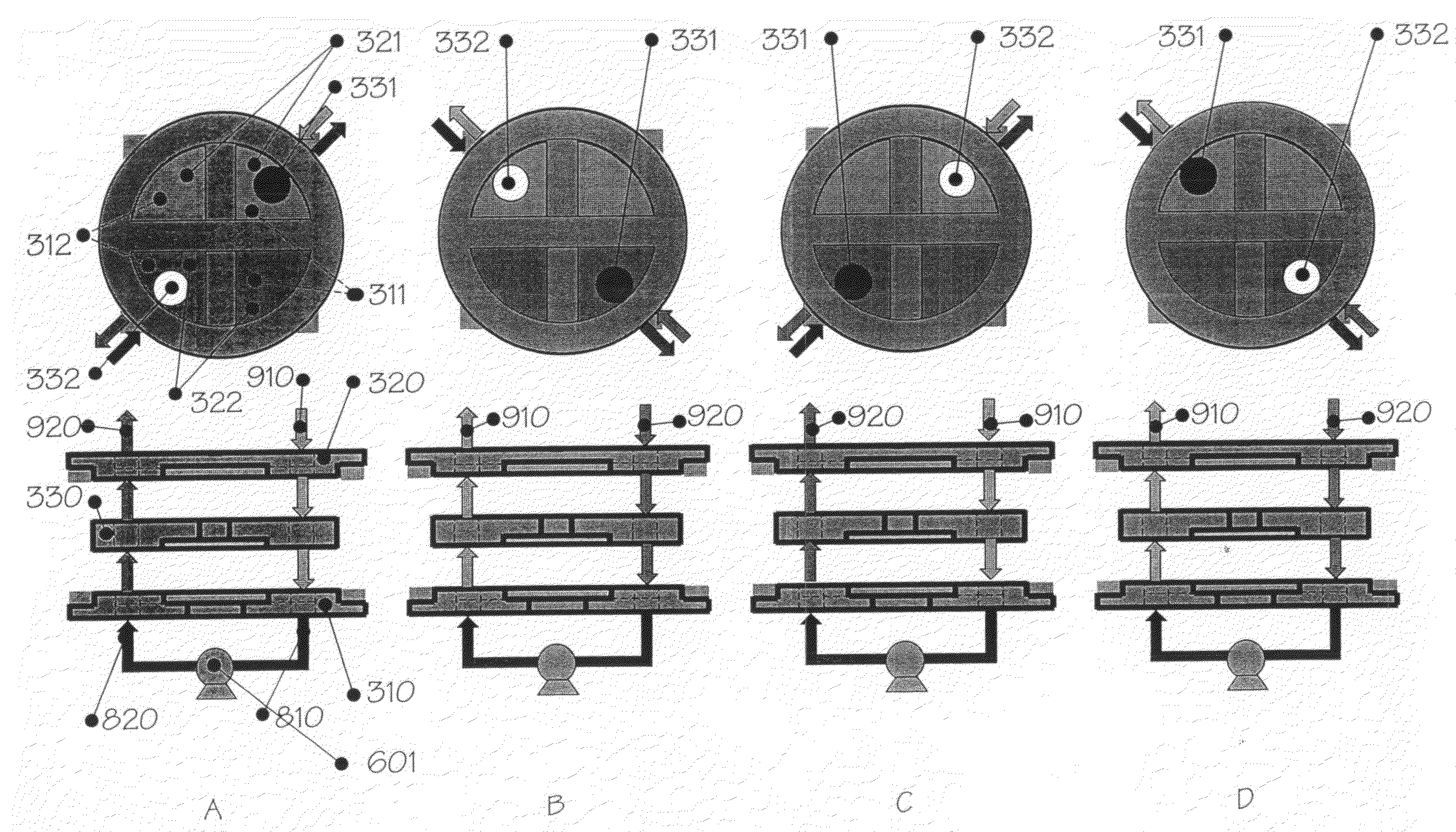
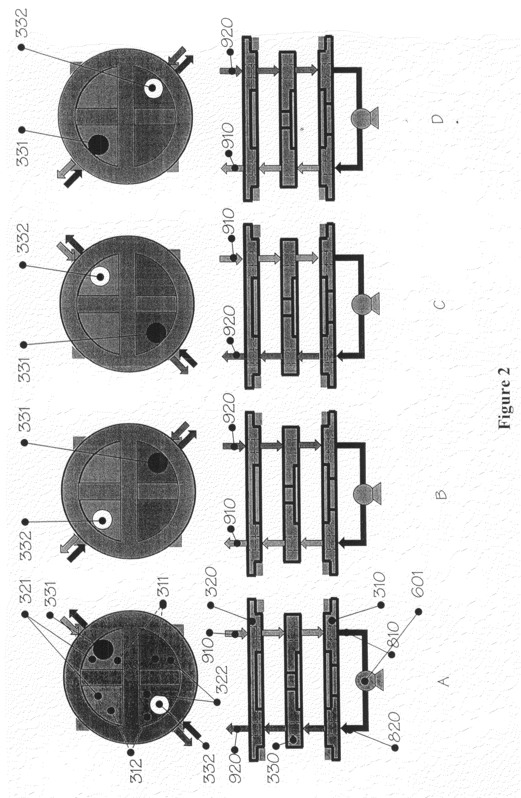
[0334]Single adsorbent bed vacuum-pressure swing adsorption process, from a starting position a compressor inlet communicates with ambient air by means of (1) a first aperture of a first valve member, (2) a first aperture of a second valve member and (3) a first through aperture of a third valve member and thereby provides a source of feed gas to the system; and a compressor outlet communicates with an adsorbent bed by means of (1) a second aperture of first valve member, (2) a second aperture of second valve member and (3) a second through aperture of third valve member and thereby provides pressurized air to adsorbent bed.

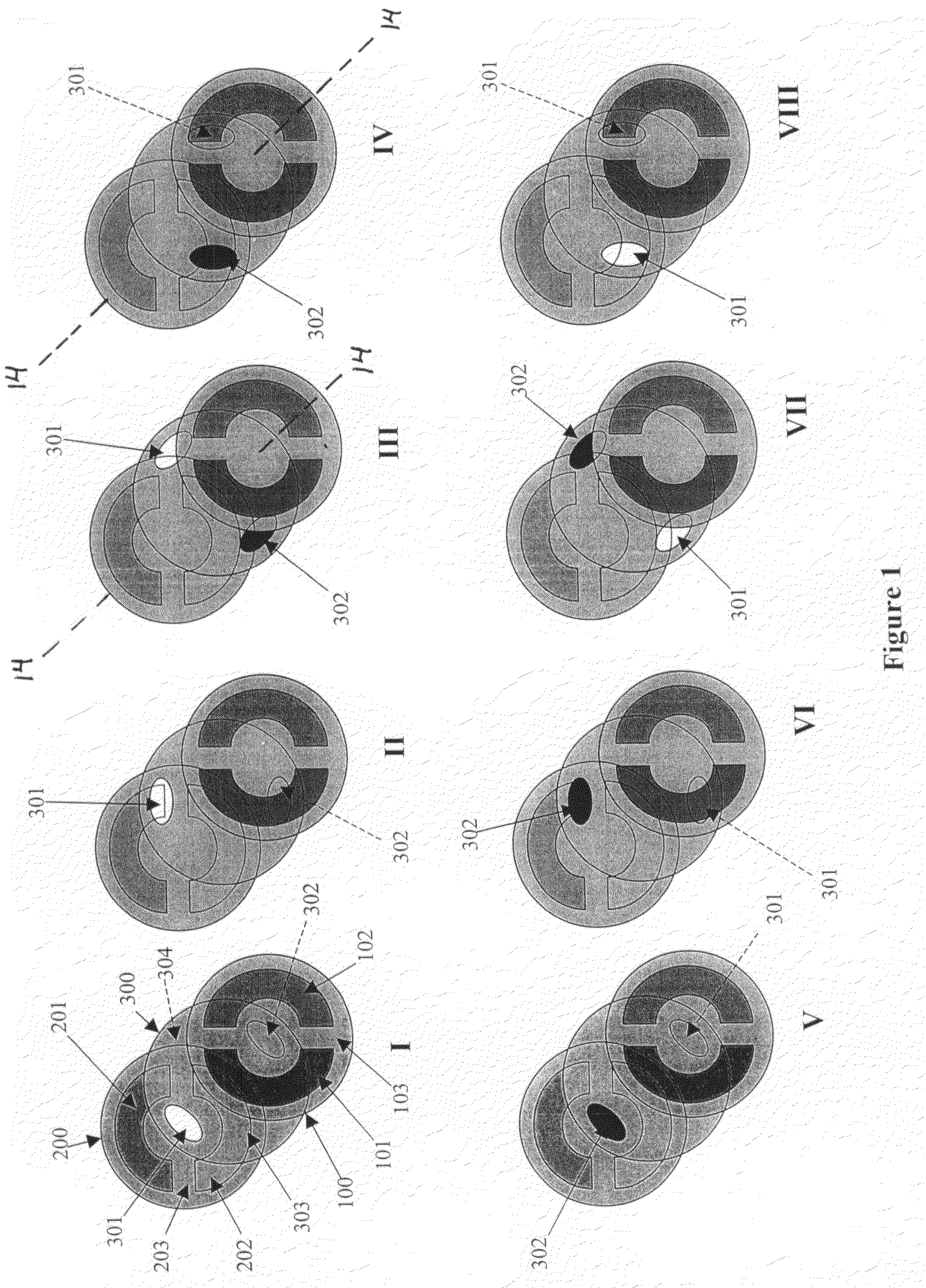
[0335]Upon relative rotation of third valve member to first valve member and second valve member wherein positional coincidence of apertures of first valve member and second valve member are greater than 0° and less than 180° angular degrees, interconnection and communication simultaneously changes and compressor inlet communicates with adsorbent bed by means of ...

example 2

[0340]Single adsorbent bed pressure swing adsorption process, from a starting position a compressor inlet communicates with ambient air and a compressor outlet communicates with adsorbent bed by means of (1) a first aperture of first valve member, (2) a first aperture of second valve member and (3) a first through aperture of third valve member and thereby provides pressurized air to an adsorbent bed; and ambient air communicates with ambient air by means of (1) a second aperture of first valve member, (2) a second aperture of second valve member and (3) a second through aperture of third valve member and thereby provides an idle position.

[0341]Upon relative rotation of third valve member to first valve member and second valve member wherein positional coincidence of through apertures of first valve member and second valve member are greater than 0° and less than 180° angular degrees, interconnection and communication simultaneously changes and compressor outlet communicates with am...

example 3

[0346]Paired adsorbent bed vacuum-pressure swing adsorption process, from a starting position a first compressor inlet communicates with ambient air, a first compressor outlet communicates with a first adsorbent bed by means of (1) a first aperture of a first valve member, (2) a first aperture of a second valve member and (3) a first aperture of a third valve member and thereby provides pressurized air to a first adsorbent bed; a second compressor inlet communicates with a second adsorbent bed by means of (1) a second aperture of first valve member, (2) a second aperture of second valve member, and (3) a second through aperture of third valve member and thereby evacuates oxygen deplete gas from a second adsorbent bed, and a second compressor outlet provides pressurized oxygen deplete gas from second adsorbent bed to ambient air.

[0347]Upon relative rotation of third valve member to first valve member and second valve member wherein positional coincidence of through apertures of first...


PUM


Abstract

A rotary valve assembly for use in a process provides fluid communication and enables variable conduit interconnection and flow passage. Process cycle time is variable by means of rotational speed of through one or more apertures of a third valve member and respective alignment with one or more apertures of a first valve member and one or more apertures of a second valve member. Process step time is variable by means of adjustable position and variable alignment of aperture(s) of the first valve member and the second valve member. The rotary valve assembly provides for gradual transition and flow passage between process steps, flow metering, mixing, reversal, or any combination thereof. Process systems including the rotary valve include an adsorption process, humidity control process, heat pump process and / or water purification process among others.

Description

CROSS-REFERENCE TO RELATED APPLICATIONS[0001]This application claims the benefit of U.S. Provisional Application No. 60 / 780,694, filed on Mar. 9, 2006.BACKGROUND OF THE INVENTION[0002]1. Field of the Invention[0003]The present invention is directed generally to a valve assembly, and more specifically, to an adjustable rotary valve assembly for selectively controlling the flow of a fluid and a fluid-flow process including said rotary valve assembly.[0004]2. Description of Related Art[0005]Previous valve assemblies are of limited use for fluid flow applications because of their lack of flow-control adaptability, reversal or metering. Generally, prior art processes employ numerous separate valves and sophisticated electronics to control the cooperation of those valves to bring about a desired process fluid flow control. This need for multiple valves and control circuitry to coordinate the operation of the many valves made process fluid control complex and expensive.[0006]For example, s...

Claims


Application Information

Patent Timeline
IPC IPC(8): F16K5/00B01D53/02
CPCF16K11/087Y10T137/0318Y10T137/86839Y10T137/86863
Inventor MICHAELS, GREGORY A.
Owner MICHAELS GREGORY A
Learn More