Up-flow residual oil hydrogenation reaction system and residual oil hydrotreatment method
A reaction system, hydrogenation treatment technology, applied in the treatment of hydrocarbon oil, petroleum industry, refining to remove heteroatoms, etc., can solve the problems of difficult temperature control, high hydrogenation activity, long service life, etc., to achieve stable temperature, The effect of raising the reaction temperature and improving the conversion ability
- Summary
- Abstract
- Description
- Claims
- Application Information
AI Technical Summary
Problems solved by technology
Method used
Image
Examples
Embodiment 1
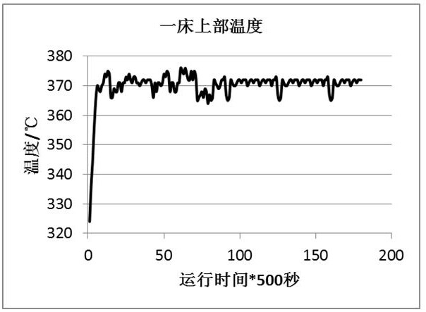
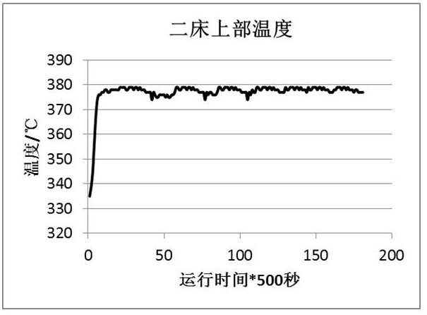
[0045] In this example, an upflow hydrogenation reactor is used to carry out the residual oil hydrotreating reaction. The upflow reactor is provided with two catalyst beds with a volume ratio of 1:1. Each catalyst bed is filled with 420 mL of catalyst, and the total amount of catalyst loaded is 840 mL. The first catalyst bed uses hydrotreating catalyst FZC-11UA, and the second catalyst bed uses hydrotreating catalyst FZC-10U. The properties of the catalysts are shown in Table 1.
[0046] The feed used is a typical Middle East residual oil, and the hydrofining reaction is carried out in the upflow residual oil hydrogenation reactor, and the upflow hydrogenation oil is obtained after mainly removing impurities such as metals. The main process conditions are shown in Table 2. The properties of the hydrogenated oil obtained in the upflow reactor are shown in Table 3.
[0047] A material distributor and a hydrogen cooling pipe are arranged between the catalyst beds of the upflow ...
Embodiment 2
[0053] In this example, an upflow hydrogenation reactor is used to carry out the residual oil hydrotreating reaction. The upflow reactor is equipped with three catalyst beds. Along the flow direction, the first catalyst bed is filled with 250 mL of catalyst, the second catalyst bed is filled with 300 mL of catalyst, and the third catalyst bed is filled with 350 mL of catalyst. The total amount is 900 mL. The first bed of the upflow reactor adopts the hydrotreating catalyst FZC-11UB, the second bed adopts the hydrotreating catalyst FZC-11UA, and the third bed adopts the hydrotreating catalyst FZC-10U.
[0054] The feed used is a typical Middle East residual oil, and the hydrofining reaction is carried out in the upflow residual oil hydrogenation reactor, and the upflow hydrogenation oil is obtained after mainly removing impurities such as metals. The main process conditions are shown in Table 4. The properties of the hydrogenated oil obtained in the upflow reactor are shown i...
Embodiment 1 and comparative example 1
[0062] Table 2 embodiment 1 and comparative example 1 main process conditions
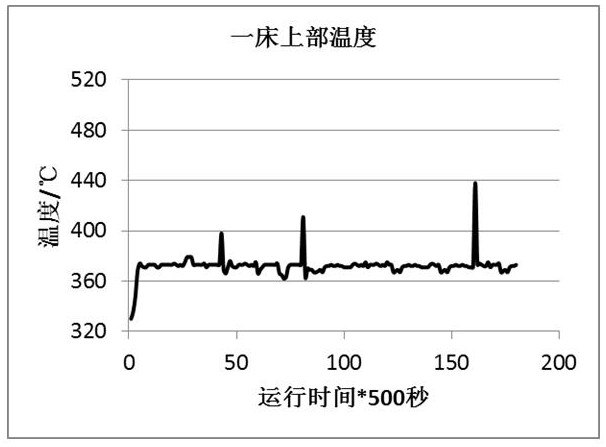
[0063] project Example 1 Comparative example 1 Upflow Catalyst Number First bed: FZC11UA / Second bed: FZC10U First bed: FZC10U / Second bed: FZC11UA Reaction pressure, MPa 17.0 17.0 Liquid hourly volumetric space velocity, h -1
0.38 0.38 Hydrogen oil volume ratio 300 300 The first bed temperature, ℃ 370 373 Second bed temperature, ℃ 378 380
[0064] Table 3 The feedstock used in Example 1 and Comparative Example 1 and the main properties of the hydrogenated oil
[0065] project Feed 1 Example 1 Comparative example 1 S, wt% 4.17 2.36 2.40 N, μg / g 3332 2353 2421 CCR, wt% 11.63 8.77 8.91 Density (20℃), kg / m 3
PUM
| Property | Measurement | Unit |
|---|---|---|
| specific surface area | aaaaa | aaaaa |
| particle diameter | aaaaa | aaaaa |
| density | aaaaa | aaaaa |
Abstract
Description
Claims
Application Information
 - R&D
- Intellectual Property
- Life Sciences
- Materials
- Tech Scout
- Unparalleled Data Quality
- Higher Quality Content
- 60% Fewer Hallucinations
Browse by: Latest US Patents, China's latest patents, Technical Efficacy Thesaurus, Application Domain, Technology Topic, Popular Technical Reports.
© 2025 PatSnap. All rights reserved.Legal|Privacy policy|Modern Slavery Act Transparency Statement|Sitemap|About US| Contact US: help@patsnap.com


