Bifocal multiorder diffractive lenses for vision correction
Inactive Publication Date: 2005-03-17
APOLLO OPTICAL SYST
View PDF91 Cites 45 Cited by
Summary
Abstract
Description
Claims
Application Information
AI Technical Summary
This helps you quickly interpret patents by identifying the three key elements:
Problems solved by technology
Method used
Benefits of technology
Benefits of technology
FIGS. 18, 19, and 20 are graphs of the efficiency versus wavelength for three multiorder diffractive structures having different values of p, an integer representing the maximum phase modulation as a multiple of 2π, where the peaks of the efficiency correspond with the peak of human perception of light for photopic and scotopic vision.
Problems solved by technology
Such bifocal refractive lenses do not utilize diffractive structures for near or distance vision correction.
Method used
Image
Click on the blue label to locate the original text in one second.
Reading with bidirectional positioning of images and text.
Examples
example 1
Consider an ophthalmic lens prescription requiring a correction of −7 diopters for distance vision, with a +2 diopter add power for near vision. Thus, the two powers (denoted by φ) of the lens are
φdistance=−7D
φnear=−5D (=−7+2)
The radial locations (rj) of the diffractive zones from the center of the lens are given by rj=2j p λ0|ϕ0|
where j is the zone number, p is the MOD number, λ0 is the design wavelength, and φ0 is the desired optical power of the lens. [See Eq. (1) of the above-incorporated U.S. patent, with φ0=1 / F0.]
In this example, λ0=555 nm (peak of photopic response). If p=11, the zone radii within a clear aperture diameter of 12 mm for the distance power are
Distance power (−7 D)ZONE NUMBER (j)ZONE RADIUS (rj)11.32071421.86777232.28754442.64142852.95320663.23507673.49428183.73554493.962142104.176465114.380313124.575088134.761902144.941660155.115104165.282856175.445444185.603315195.756859205.906413
Similarly, for the near power, the zone radii are
Near power (−5...
example 2
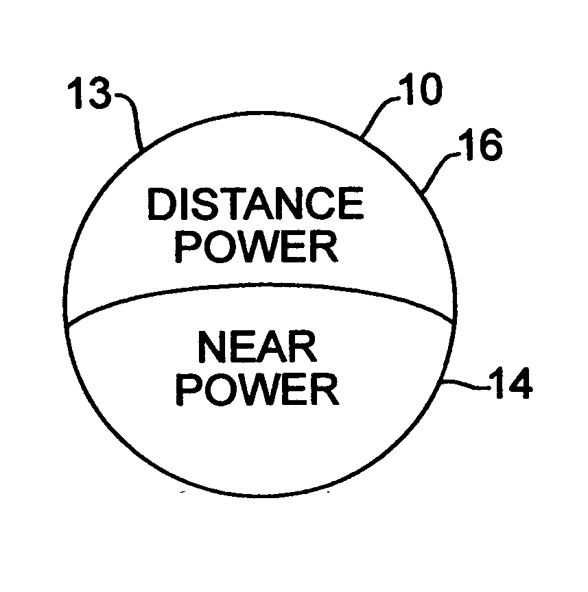
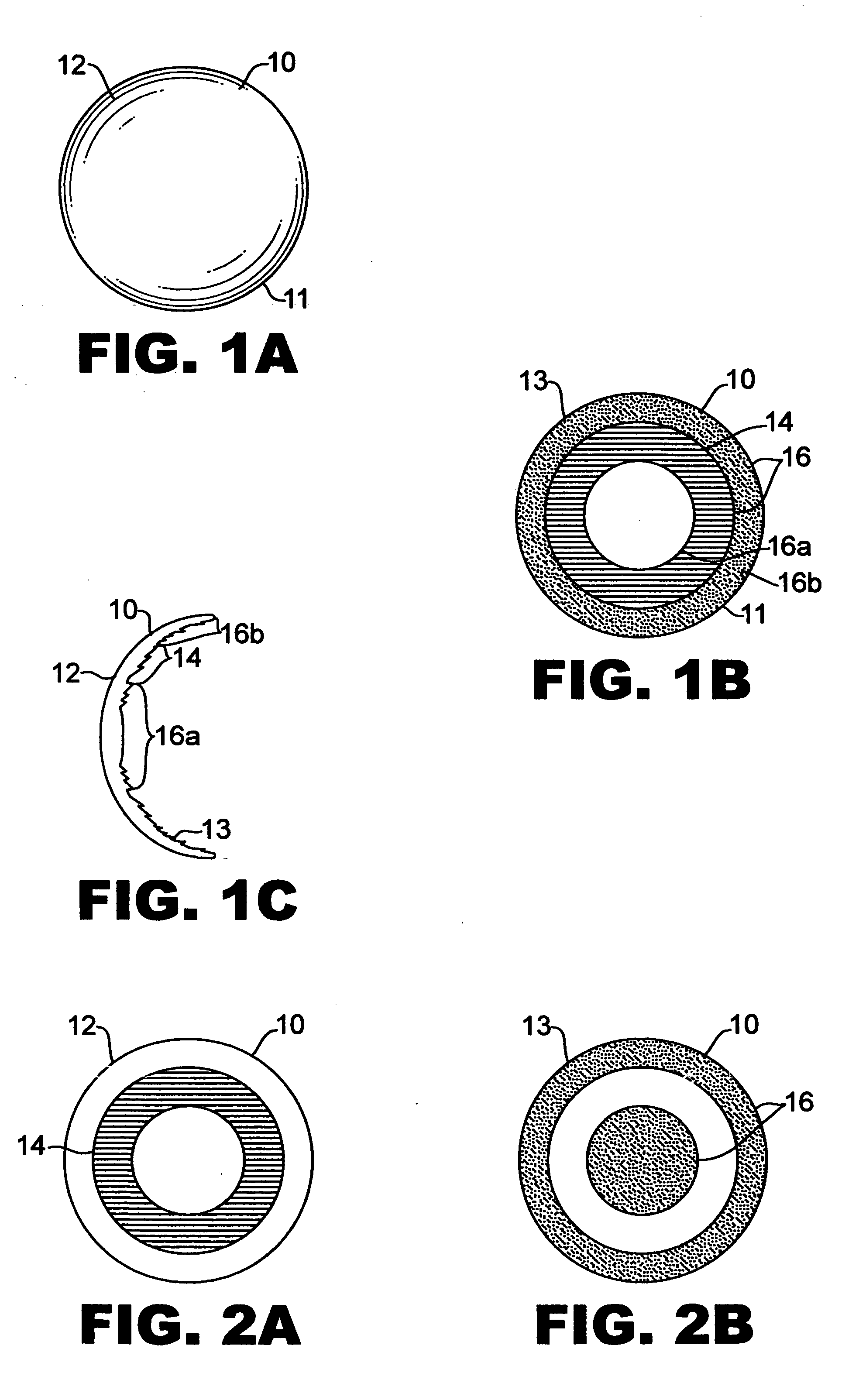
To construct the bifocal MOD lens along the same surface, as shown in FIGS. 1A-1C, all the diffractive power is contained in circular / annular regions of one surface of the lens. The distance power is contained in regions 16a and 16b of FIG. 1B, while the near power is contained in region 14. We choose the radius of region 16a to be 2 mm, the outer radius of region 14 to be 4 mm and the outer radius of region 16b to be 6 mm. Then, the zone locations for the bifocal lens are the radii of the individual power components that lie within these region boundaries. There are no diffractive zones on the other side of the lens.
Zone locations for bifocal MOD lensZONE NUMBER (j)ZONE RADIUS (rj)11.320714distance21.867772distance32.209977near42.706658near53.125380near63.494281near73.827793near84.176465distance94.380313distance104.575088distance114.761902distance124.941660distance135.115104distance145.282856distance155.445444distance165.603315distance175.756859distance185.906413distance
Note th...
example 3
Another option is to place the near power on one surface of the lens and the distance power on the other surface, as in the lens of FIGS. 2A and 2B. In this embodiment, the zone locations are
ZONE NUMBER (j)ZONE RADIUS (rj)First Surface12.209977near22.706658near33.125380near43.494281near53.827793nearNo diffractive zones for radius less than 2.0 mmor radius greater than 4.0 mm.Second Surface11.320714distance21.867772distance34.176465distance44.380313distance54.575088distance64.761902distance74.941660distance85.115104distance95.282856distance105.445444distance115.603315distance125.756859distance135.906413distanceNo diffractive zones for radius greater than 2.0 mmand less than 4.0 mm.
For all of the above examples, the height of the zones is given by h=p λ0nlens(λ0)-nmedium(λ0)
[See Eq. (4) of above-incorporated U.S. patent.]
If the lens is in air, then nmedium(λ0)=1.0. Also, if the lens is constructed of a material with a refractive index of nlens(λ0)=1.5, this results in a hei...
PUM
Abstract
A bifocal multiorder diffractive lens is provided having a lens body with one or more first regions having a first multiorder diffractive structure providing near vision correction, and one or more second regions having a second multiorder diffractive structure providing distance vision correction, in which the lens defines an aperture divided between the first and second regions. Such one or more first regions may represent one or more annular rings, or other portion of the lens, and the second region may occupy the portion of the lens aperture outside the first region. The lens body may be provided by a single optical element or multiple optical elements. When multiple optical elements are used, the multiorder diffractive structures may be located along an interior surface of the lens. In other embodiments, a bifocal multiorder diffractive lens is provided by a single or multiple element lens body having a multiorder diffractive structure for distance vision correction and one or more refractive regions to add power for near vision correction, or a single or multiple element lens body shaped for refractive power for distance vision correction and a multiorder diffractive structure for add power for near vision correction. The lens may represent a contact lens, a spectacle lens, or the optic portion of an intraocular implant (IOL). Multiorder diffractive structures may be optimized for performance for photopic and scotopic vision.
Description
FIELD OF THE INVENTION The present invention related to multiorder diffractive lenses for vision correction, and particularly to bifocal multiorder diffractive lenses for therapeutic vision correction at distance and near vision correction suitable for use with a variety of vision correction applications, such as intraocular implants (IOLs), contact lenses, or spectacle (eyeglass) lenses. BACKGROUND OF THE INVENTION Multiorder diffractive (MOD) lenses are useful for bringing a plurality of spectral components of different wavelengths to a common focus, and are described in U.S. Pat. No. 5,589,982, which is herein incorporated by reference. The MOD lens has a structure of multiple annular zones having step heights defining zone boundaries, which diffract light of each of the wavelengths in a different diffractive order to a common focus. Such a MOD lens has not been applied to bifocal optics for vision correction. Conventional bifocal optics for spectacles are provided by lenses h...
Claims
Application Information
Patent Timeline
Application Date:The date an application was filed.
Publication Date:The date a patent or application was officially published.
First Publication Date:The earliest publication date of a patent with the same application number.
Issue Date:Publication date of the patent grant document.
PCT Entry Date:The Entry date of PCT National Phase.
Estimated Expiry Date:The statutory expiry date of a patent right according to the Patent Law, and it is the longest term of protection that the patent right can achieve without the termination of the patent right due to other reasons(Term extension factor has been taken into account ).
Invalid Date:Actual expiry date is based on effective date or publication date of legal transaction data of invalid patent.
Patent Type & AuthorityApplications(United States)

