Unlock instant, AI-driven research and patent intelligence for your innovation.

Image quality correction apparatus and image quality correction method

a technology of image quality and apparatus, applied in the field of apparatus and image quality correction methods, can solve the problems of inability to achieve optimum correction for input image, inability to accurately calculate the amount of correction, undetectable luminous values of characters, etc., and achieve the effect of correcting image quality

Inactive Publication Date: 2005-03-17
PANASONIC CORP
View PDF3 Cites 28 Cited by
  • Summary
  • Abstract
  • Description
  • Claims
  • Application Information

AI Technical Summary

Benefits of technology

"The present invention provides an image quality correction apparatus and method that can effectively correct image quality even when there are degradation factors present in the image data. The apparatus includes an image data selecting unit that removes degradation factor data from the input image data, a luminous histogram formation unit that creates a luminous histogram of the image data, a correction amount calculation unit that calculates an amount of correction based on the luminous histogram, and an image quality correction unit that uses the calculated correction amount to correct the input image data. The apparatus can also identify and remove specific degradation factors that may affect image quality, such as pixel data that constitute a character area. The invention provides a more efficient and effective solution for improving image quality, particularly in cases where there are multiple degradation factors present in the image data."

Problems solved by technology

In the conventional construction, however, when a character area, such as subtitles of a movie, exists in an input image, the luminous values of the characters are undesirably counted during formation of the luminous histogram, although only the image data in the image area excluding the character area should be corrected.
Therefore, a luminous histogram corresponding to only the image area of the input image cannot be formed, and an accurate amount of correction cannot be calculated.
As a result, optimum correction for the input image cannot be carried out.
Therefore, when the amount of correction is calculated on the basis of the luminous histogram, erroneous correction of image quality might be carried out, resulting in degradation in image quality due to the correction.

Method used


Image

  • Image quality correction apparatus and image quality correction method
  • Image quality correction apparatus and image quality correction method
  • Image quality correction apparatus and image quality correction method

Examples


embodiment 1

Hereinafter, an image quality correction apparatus and an image quality correction method according to a first embodiment of the present invention will be described with reference to the drawings.

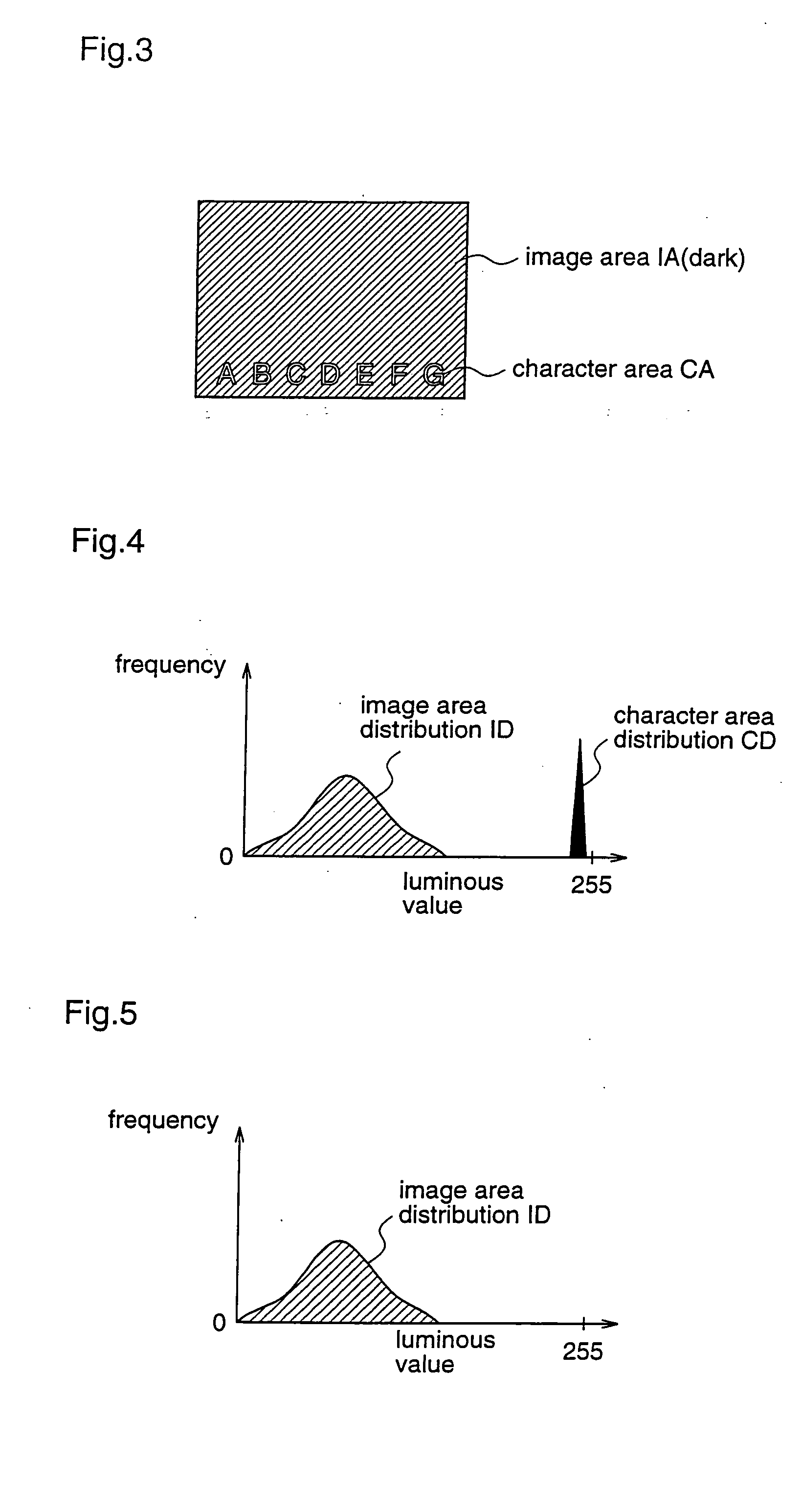
The image quality correction apparatus and method according to the first embodiment performs correction of image quality by using a luminous histogram corresponding to only an image area which is obtained by excluding a character area from input image data. The character area is an area of data which constitute characters and the like and are included in the input image, such as subtitles of a movie, and this data area appears as an outstanding shape in the luminous histogram.

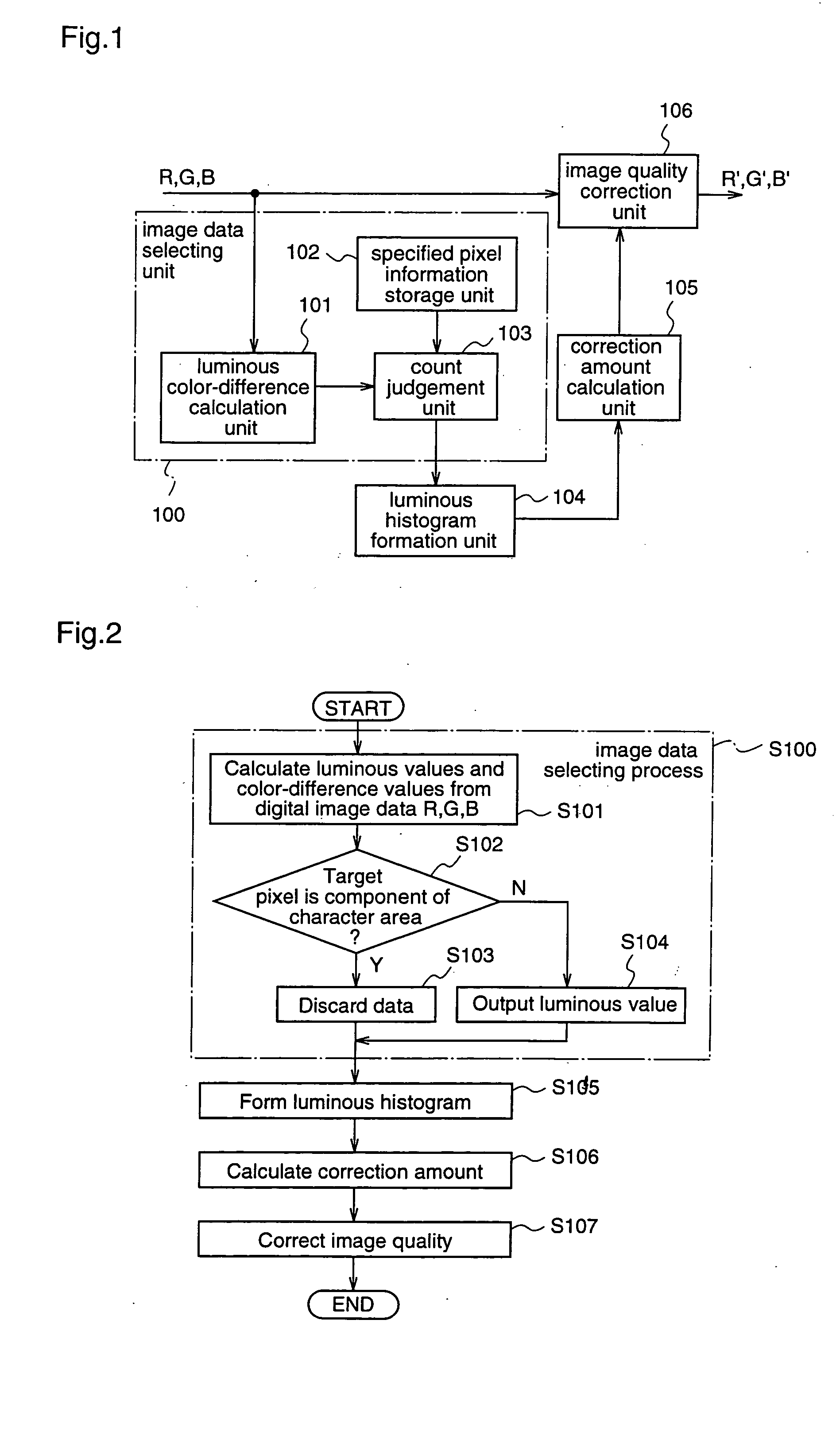
FIG. 1 is a block diagram illustrating an example of an image quality correction apparatus according to the first embodiment of the present invention.

With reference to FIG. 1, the image quality correction apparatus according to the first embodiment comprises a luminous color-difference calculation unit 101, a spe...

embodiment 2

Hereinafter, an image quality correction apparatus and an image quality correction method according to a second embodiment of the present invention will be described with reference to the drawings.

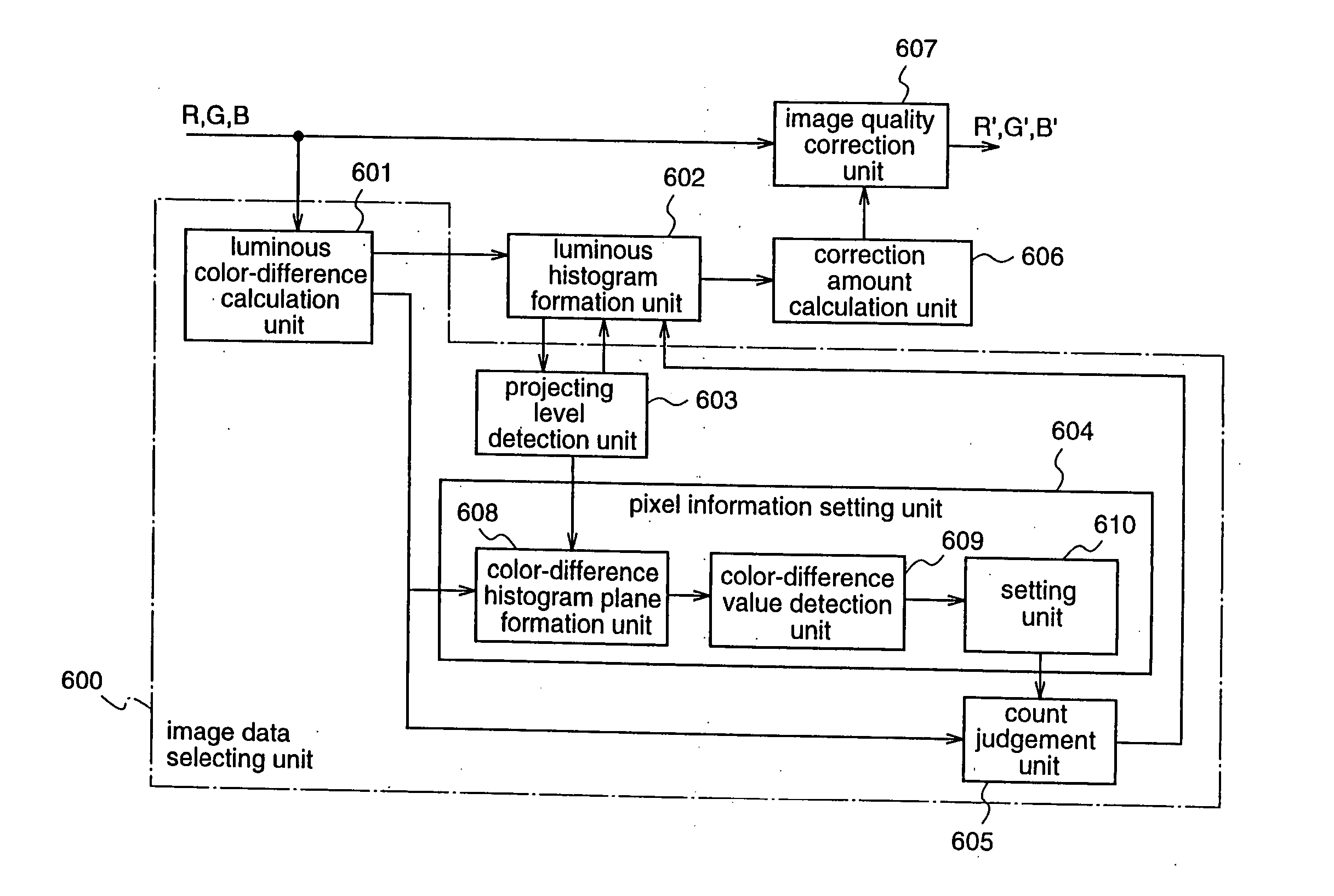
The image quality correction apparatus and method according to the second embodiment are different from those of the first embodiment in that, when there is a projecting gradation level (hereinafter referred to as projecting level) in a luminous histogram that is formed from input image data, a luminous value and color-difference values to be used for judging as to whether a target pixel is a component of a character area or not is obtained from a luminous value having the detected level.

FIG. 6 is a block diagram illustrating an example of an image quality correction apparatus according to the second embodiment.

As shown in FIG. 6, the image quality correction apparatus according to the second embodiment is provided with a luminous color-difference calculation unit 601, a luminous his...

embodiment 3

Next, a modification of the processing by the pixel information setting unit 604 according to the second embodiment will be described as a third embodiment of the present invention.

With reference to FIG. 11, in the pixel information setting unit 604 according to the third embodiment, the color-difference value detection unit 609 divides the color-difference histogram plane formed by the color-difference histogram plane formation unit 608 at predetermined intervals, and judges whether or not a representative value that is calculated from the frequencies of the color-difference values in each of the divided areas DA is equal to or larger than a predetermined threshold value, and detects the color-difference values in the divided area DA having the representative value equal to or larger than the predetermined threshold value. The intervals at which the color-difference histogram plane is divided may be adjusted according to the size of the character area included in the input image...


PUM


Abstract

A count judgement unit judges whether or not a luminous value and color-difference values calculated by a luminous color-difference calculation unit are those of a pixel as a component of a character area, and outputs only luminous values of pixels other than pixels as components of the character area, to a luminous histogram formation unit. Then, a correction amount calculation unit and an image quality correction unit perform correction of image quality of input image data on the basis of the luminous histogram that is formed by the luminous histogram formation unit using the luminous values outputted from the count judgement unit. Therefore, even when information that adversely affects image quality correction, such as characters, is mixed in the input image, appropriate correction can be performed on only the image area to be corrected.

Description

FIELD OF THE INVENTION The present invention relates to an apparatus and a method for correcting image quality and, more particularly, to those for automatically correcting gradation of an input image in a digital image processing apparatus. BACKGROUND OF THE INVENTTON Conventionally, as a technique for correcting an image, a method disclosed in Japanese Published Patent Application No. 2002-172423 (Pages 14˜16, FIGS. 1˜4) has been generally known. This method includes calculating luminous values of pixels of an input image, creating a luminous histogram illustrating the total sum of pixels having the same luminous value, and subjecting all of the pixels to a correction process that optimizes the shape of the created luminous histogram. The conventional method will be described with reference to FIG. 15. FIG. 15 is a block diagram illustrating a conventional image quality correction apparatus. As shown in FIG. 15, the conventional image quality correction apparatus comprises an ...

Claims


Application Information

Patent Timeline
Patent Type & Authority Applications(United States)
IPC IPC(8): G06T5/40G06T1/00G06V30/10H04N1/40H04N1/407H04N1/46H04N1/60H04N5/20H04N23/76
CPCG06K9/325G06K9/4647G06T2207/10024G06T5/009G06T5/40G06K9/4652G06V20/62G06V30/10G06V30/18095G06V30/18105G06T5/92
Inventor MARUOKA, KAZUTAKA
Owner PANASONIC CORP