Reinforced locking connector

a locking connector and reinforcement technology, applied in the direction of coupling device connection, coupling parts engagement/disengagement, incorrect coupling prevention, etc., can solve the problems of personal injury, latching mechanism failure, plastic tends to fatigue from deformation, etc., to prevent accidental disconnection and reinforce the connection

Inactive Publication Date: 2005-03-17
AMPHENOL ALDEN PROD CO
View PDF35 Cites 13 Cited by
  • Summary
  • Abstract
  • Description
  • Claims
  • Application Information

AI Technical Summary

Benefits of technology

[0007] The present invention provides a reinforced locking connector. The present invention combines a self-latching arrangement with a manual de-coupling arrangement in a connector system. The locking connector comprises first and second tubular connector bodies having telescopingly engaged body portions and axially mating contacts, an annular collar rotatively held on the first body encircling the telescoping body portions and a spring inside the collar. The ends of the spring are confined between the first body and the collar so as to yieldingly resist rotation of the collar relative to the first body. Axially aligned tabs are provided on the collar and the second body for latching the first body and the second body together through a predetermined range of forces. The tabs include opposed flaring cam surfaces, which cause the collar to rotate relative to the second body as the first and second body are telescoped to a mated contact position. The cam surfaces guide the collar tab around the body tab, and the coiled spring yields as the collar is rotated by the cam tabs during contact mating to allow the collar tab to slide past the body tab. The spring then rotates the collar tab to a latching position axially behind the body tab, thereby locking the connector bodies in mated contact position. The collar tab and the cam tab are configured to reinforce the connection between the first body and the second body to prevent accidental disconnection of the first and second bodies.

Problems solved by technology

If such a deforming latching body is frequently engaged and disengaged, the plastic tends to fatigue from the deformation.
As a result, the latching mechanism eventually fails.
For example, requirements exist in some industries that a mated pair of connectors disengage (or break away) before the cable is damaged, the connector pair is damaged, personnel trip over the cord, electrodes connected to the connector are stripped off a patient (in medical applications) and / or attached equipment, such as an electronic device, falls and becomes damaged, falls from a shelf and crashes to the floor or falls in such a way to cause personal injury.

Method used


Image

  • Reinforced locking connector
  • Reinforced locking connector
  • Reinforced locking connector

Examples


Embodiment Construction

[0017] The present invention provides a self-latching connector system including one or more components configured to control the breakaway force of the connector system. The invention will be described below relative to illustrative embodiments. Those skilled in the art will appreciate that the present invention may be implemented in a number of different applications and embodiments and is not specifically limited in its application to the particular embodiments depicted herein.

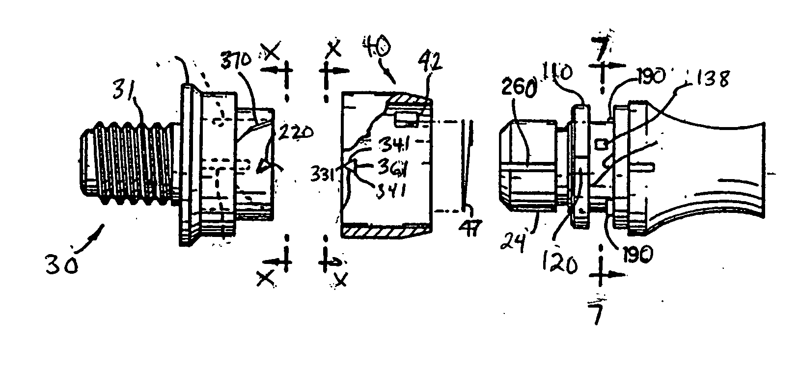
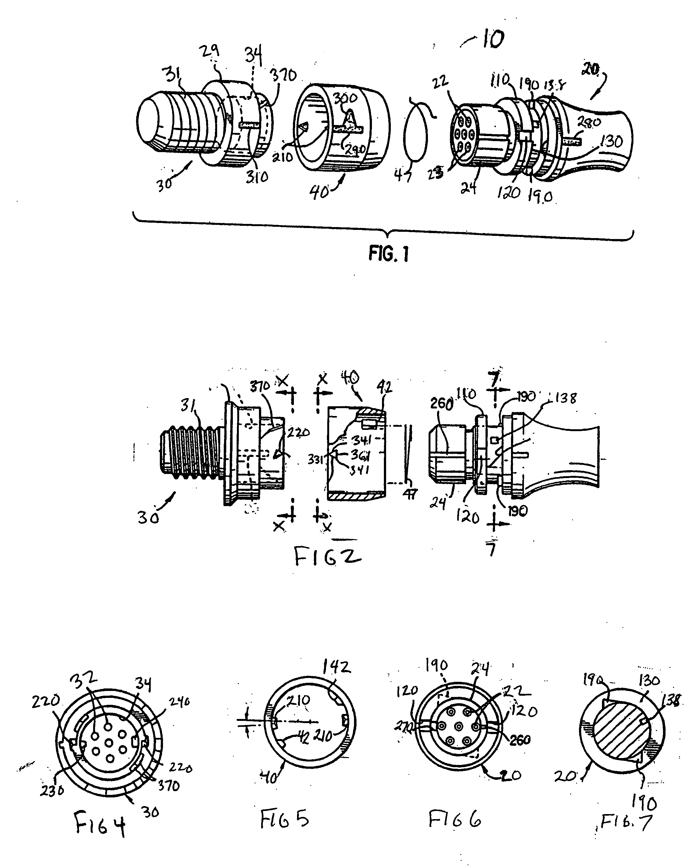
[0018]FIG. 1 illustrates a locking connector 10 according to an illustrative embodiment of the invention. According to the illustrative embodiment, the connector 10 is used in an electrical application, though one skilled in the art will recognize that the connector can be implemented in any suitable system. The connector 10 comprises a first connector body or plug 20 and a second connector body or receptacle 30 configured to receive and / or engage the first connector body 20. According to the illustrative ...


PUM


Abstract

A locking connector system includes a first body having a rotatable collar mounted thereon and a second body configured to mate with the first body, including one or more components configured to control the breakaway force of the first and second bodies. The first and second bodies include telescopingly engaged body portions and axially mating contacts. The connector system further includes an annular collar encircling the telescoping body portions and rotatively held on the first body and a spring inside the collar. The ends of the spring are confined between the first body and the collar so as yieldingly to resist rotation of the collar relative to the first body. Axially aligned tabs are provided on the collar and the second body for latching the first body and the second body together through a predetermined range of forces. The tabs include opposed flaring cam surfaces, which cause the collar to rotate relative to the second body as the first and second body are telescoped to a mated contact position and at least one tab includes an angled back surface. The cam surfaces guide the collar tab around the body tab, and the coiled spring yields as the collar is rotated by the cam tabs during contact mating to allow the collar tab to slide past the body tab. The spring then rotates the collar tab to a latching position axially behind the body tab, thereby locking the connector bodies in mated contact position.

Description

RELATED APPLICATIONS [0001] The present invention is a continuation-in-part of U.S. patent application Ser. No. 10 / 202,514, filed Jul. 23, 2002, the contents of which are herein incorporated by reference.FIELD OF THE INVENTION [0002] The present invention relates to an automatically locking connector system for joining a first connector body with a second connector body. BACKGROUND OF THE INVENTION [0003] Automatically locking connector systems are used for a variety of applications, such as electrical, fluidic, mechanical, optical, hydraulic or pneumatic systems, to provide a connection between various components and devices. A typical connector may comprise a female connector assembly and a male connector assembly that are designed to be engaged and disengaged with one another. Prior patents describe a coupling mechanism, having one coupler half that is inserted into the other half and a sleeve on one half, which rotates against a torsional spring force as a result of the camming ...

Claims


Application Information

Patent Timeline
Patent Type & Authority Applications(United States)
IPC IPC(8): H01R13/58H01R13/623H01R13/635H01R13/64
CPCH01R13/58H01R13/623Y10S439/923H01R13/64H01R13/635
Inventor THURSTON, BRYAN A.THURSTON, CONSTANCE E.
Owner AMPHENOL ALDEN PROD CO
Why Eureka
Try Eureka