
Method of and apparatus to restore audio data

a high-frequency moving picture and audio data technology, applied in the field of audio compression/decoding system, can solve the problems of more high-frequency regions of mp3 audio data lost, and the sbr method has the disadvantage of increasing the amount of calculation by using post-processors

Inactive Publication Date: 2005-03-17
SAMSUNG ELECTRONICS CO LTD
View PDF7 Cites 31 Cited by
  • Summary
  • Abstract
  • Description
  • Claims
  • Application Information

AI Technical Summary

Benefits of technology

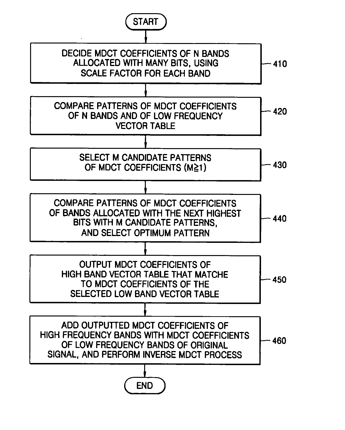
[0012] The foregoing and/or other aspects and advantages of the present general inventive concept are achieved by providing a method of restoring compressed audio, including: setting MDCT (modified discrete cosine transform) coefficients of low bands and high bands of an audio signal based on scale factor information of each band; extracting MDCT coefficients of low bands per band based on scale factors of each band after dequantizing an inputted compressed audio bitstream; selecting the MDCT coefficients of the low bands, which is set in the operation of setting the MDCT coefficients of the low bands and the high bands, that corresponds to patterns of MDCT coefficients of low bands of the inputted compressed audio bitstream, and selecting the MDCT coefficients of the high bands, which is set in the operation of setting the MDCT coefficients of the low bands and the high bands, that matches with the MDCT coefficients of the selected low bands; and performing an inverse MDCT by adding the MDCT coefficients of the high bands select

Problems solved by technology

However, the more MP3 audio data is compressed, the more high frequency regions of the MP3 audio data are lost.
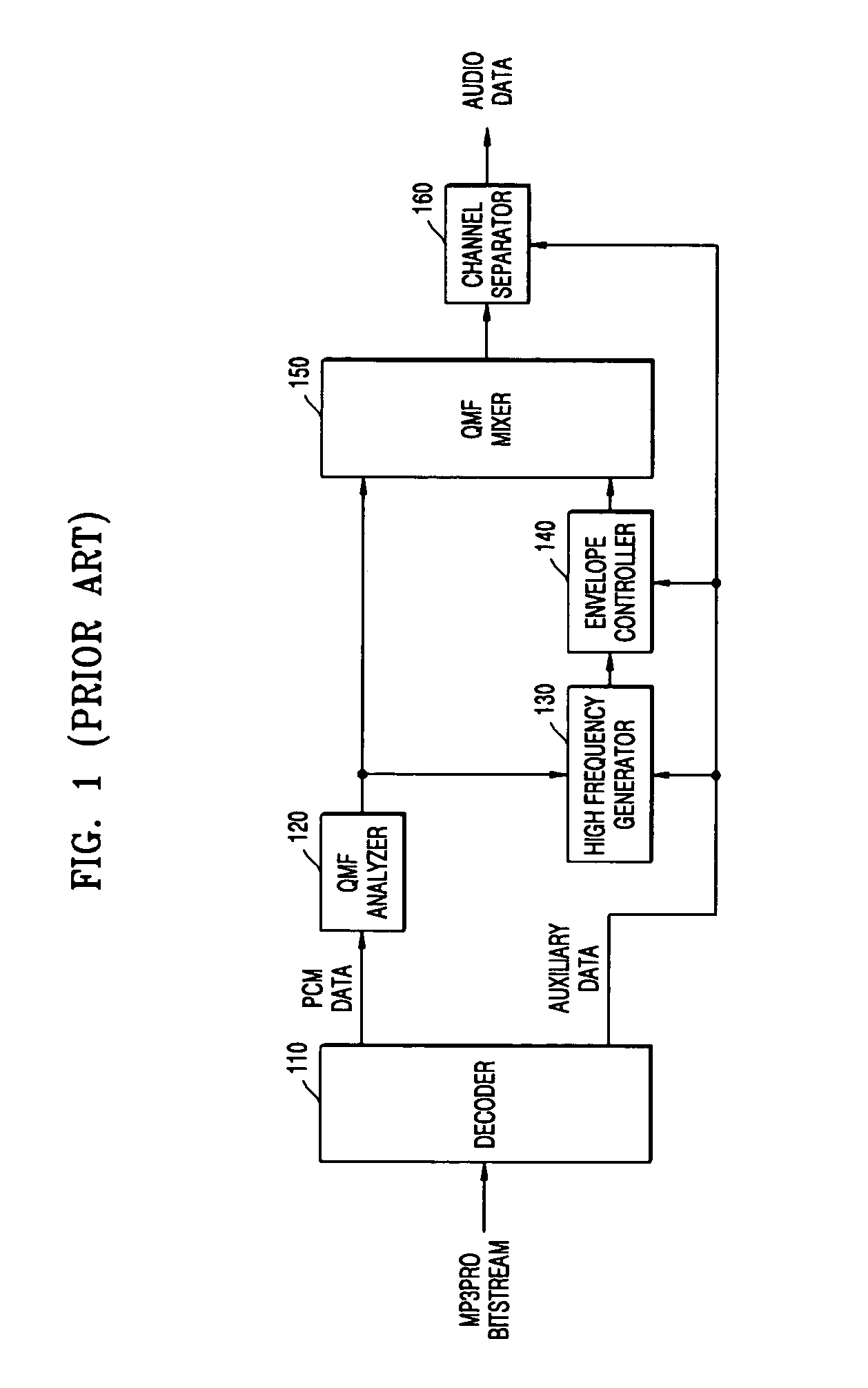
Therefore, the SBR method has a disadvantage of increasing an amount of calculation by using the post-processors.
Therefore, the mp3PRO decoding of the SBR method using the post-processors algorithm may include an error in the restored high frequency component since the high frequency components are restored from low frequency components that are allocated different numbers of bits for each band.

Method used


Image

  • Method of and apparatus to restore audio data
  • Method of and apparatus to restore audio data
  • Method of and apparatus to restore audio data

Examples


Embodiment Construction

[0020] Reference will now be made in detail to the embodiments of the present general inventive concept, examples of which are illustrated in the accompanying drawings, wherein like reference numerals refer to the like elements throughout. The embodiments are described below in order to explain the present general inventive concept by referring to the figures.

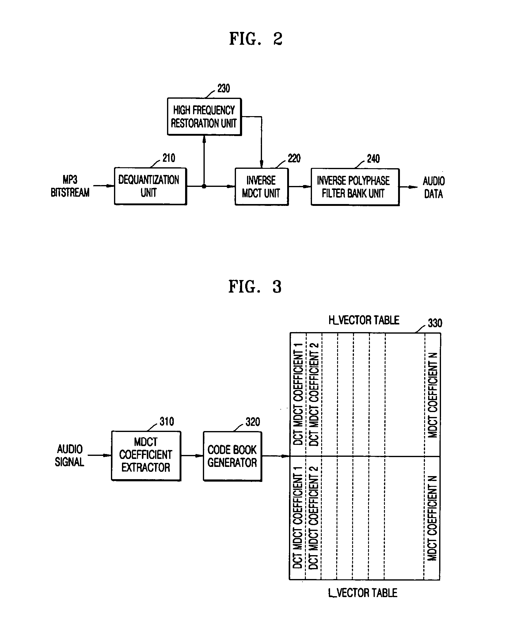
[0021]FIG. 2 is a block diagram of an apparatus to restore audio data according to an embodiment of the present general inventive concept. First, the apparatus to restore audio data receives moving picture experts group audio layer 3 (MP3) audio data output from an audio encoder (not shown). Here, the audio encoder compresses audio data in an MP3 format. In the compression process, an audio signal is divided into subbands via 32 filter banks. Then, the subbands are converted into frequency bands having narrower widths than those of the subbands using MDCT. Afterwards, data of each frequency band are quantized using MDCT coeffi...


PUM


Abstract

A method of and an apparatus to restore high frequency of a moving picture experts group audio layer 3 (MP3) audio signal within a decoder. The method includes: setting modified discrete cosine transform (MDCT) coefficients of low bands and high bands of an audio signal, based on scale factor information of each band; extracting MDCT coefficients of low bands per band based on scale factors of each band after dequantizing inputted compressed audio bitstream; selecting the MDCT coefficients of the set low bands that corresponds to patterns of MDCT coefficients of low bands of the inputted compressed audio bitstream, and selecting the MDCT coefficients of the high bands that matches with the MDCT coefficients of the selected low bands; and performing an inverse MDCT by adding the MDCT coefficients of the selected high bands with the MDCT coefficients of the low bands.

Description

CROSS-REFERENCE TO RELATED APPLICATIONS [0001] This application claims the priority of Korean Patent Application No. 2003-63474, filed on Sep. 13, 2003, in the Korean Intellectual Property Office, the disclosure of which is incorporated herein in its entirety by reference. BACKGROUND OF THE INVENTION [0002] 1. Field of the Invention [0003] The present general inventive concept relates to an audio compressing / decoding system, and more particularly, to a method of restoring a high frequency moving picture experts group audio layer 3 (MP3) audio signal within a decoder, and an apparatus thereof. [0004] 2. Description of the Related Art [0005] Generally, moving picture experts group (MPEG) audio is a standard used for high quality, high efficiency encoding, and is regulated by the international organization for standardization / international electrotechnical commission (ISO / IEC). MPEG audio combined with MPEG video makes possible highly efficient compression of multimoving information, a...

Claims


Application Information

Patent Timeline
IPC IPC(8): G10L21/02G11B20/02
CPCG10L21/038G11B20/02
Inventor OH, YOON-HARK
Owner SAMSUNG ELECTRONICS CO LTD
Learn More