
Cutter unit, half-cutting mechanism, and tape printer

a cutting mechanism and tape printer technology, applied in the direction of printing, metal working apparatus, other printing apparatus, etc., can solve the problems of increased manufacturing cost, increased frame manufacturing cost, increased weight of cutting apparatus, etc., and achieve the effect of simple frame structure and strong frame structur

Inactive Publication Date: 2005-03-24
SEIKO EPSON CORP +1
View PDF6 Cites 20 Cited by
  • Summary
  • Abstract
  • Description
  • Claims
  • Application Information

AI Technical Summary

Benefits of technology

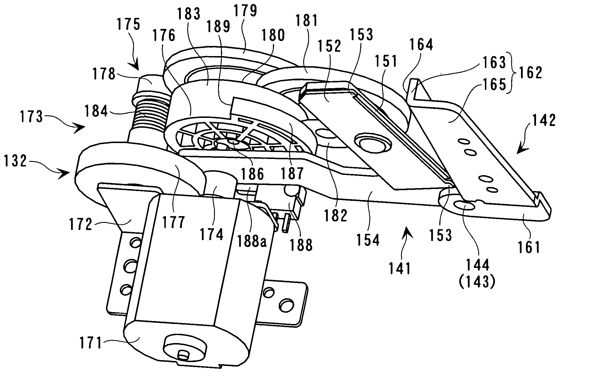
The invention provides a cutter unit with a simple yet strong frame structure that can withstand a force during a half-cutting operation. The cutter unit includes a full cutter and a half cutter, with a blade-receiving member for receiving the cutting blade when operated. The half-cutting mechanism is designed to precisely control the gap between the cutting blade and the blade-receiving member. The cutter unit also includes a tape-discharging means to prevent the tape medium from jamming and double cutting. The half-cutting mechanism includes a cutting blade with a straight-tooth blade portion and a blade-receiving member for receiving the cutting blade. The half-cutting mechanism further includes a pair of regulating members for regulating the gap between the blade portion and the blade-receiving surface.

Problems solved by technology

However, when the frame is thickened, as in the former case, the manufacturing cost of the frame is increased, and the weight of the cutting apparatus is increased.
In the latter case, since the number of components is increased, the manufacturing cost is increased, and management of the components is complicated during the manufacturing process of the apparatus.
This decreases the assembly efficiency of the cutting apparatus.

Method used


Image

  • Cutter unit, half-cutting mechanism, and tape printer
  • Cutter unit, half-cutting mechanism, and tape printer
  • Cutter unit, half-cutting mechanism, and tape printer

Examples


Embodiment Construction

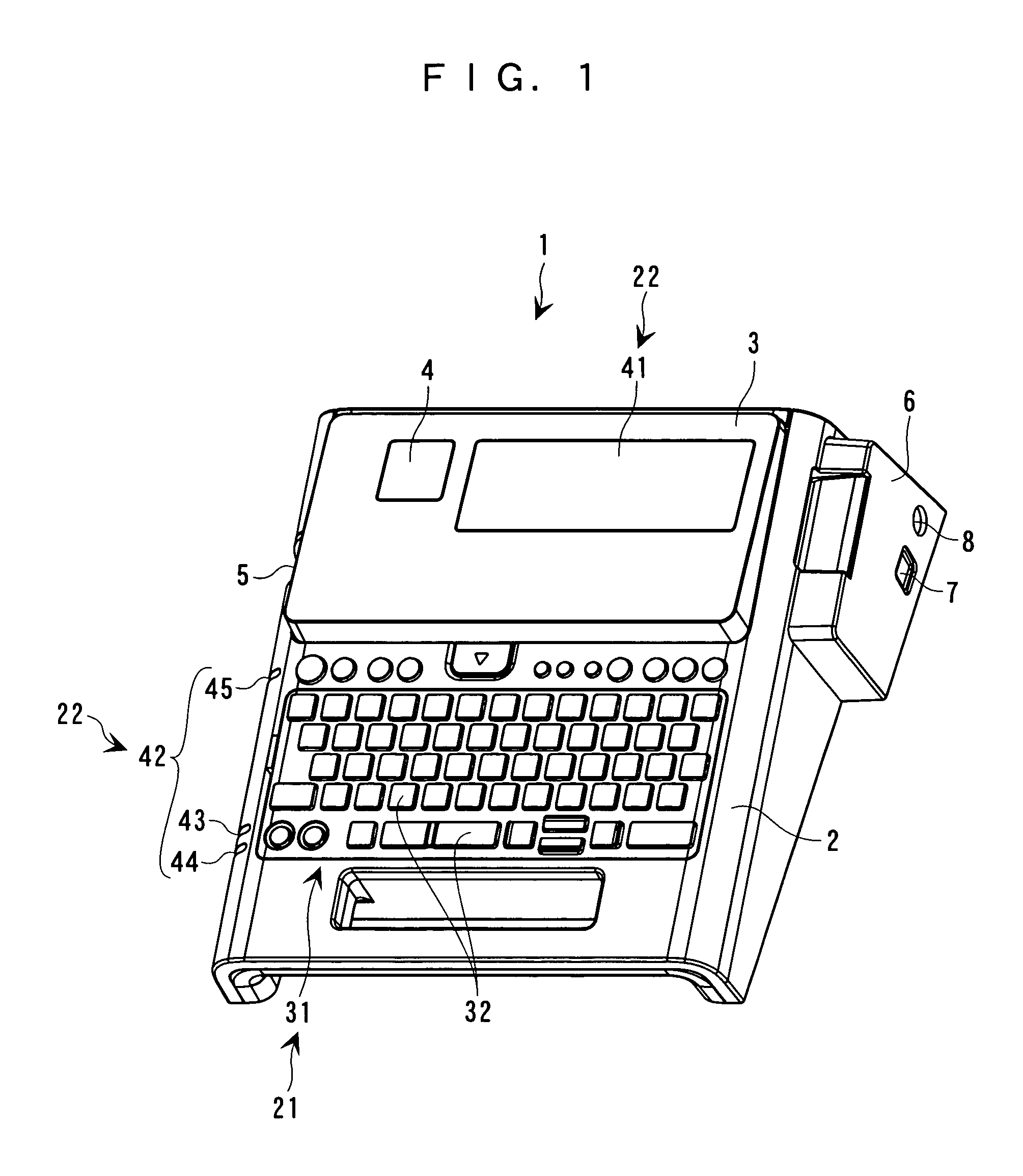
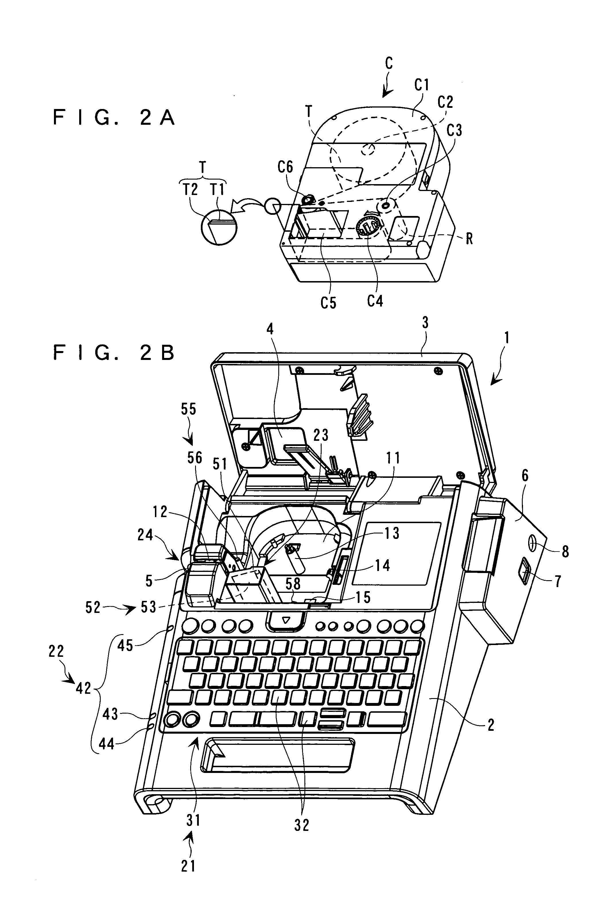
[0051] A tape printer according to an embodiment of the this invention will be described in detail below with reference to the attached drawings. A tape printer of this embodiment performs printing on a tape medium contained in a tape cartridge, and then cuts the tape medium into tape pieces.

[0052]FIG. 1 is an external perspective view of the entire tape printer of the embodiment, and FIG. 2B is an external perspective view of the tape printer in which a cover is opened. As shown in FIGS. 1 and 2B, a tape printer 1 has an outer shell defined by a printer case 2. A keyboard 31 is provided at the upper front of the printer case 2, and a cover 3 having a display 41 is provided in the upper rear of the printer case 2. The cover 3 has, on the left side of the display 41, a window 4 through which a tape cartridge C loaded in a cartridge compartment 11, which will be described later, is visible.

[0053] A tape exit 5 through which a printed tape medium T is discharged is provided in the le...


PUM

PropertyMeasurementUnit
depthaaaaaaaaaa
of timeaaaaaaaaaa
force-cutting pressureaaaaaaaaaa

Abstract

A cutter unit includes a cutter frame, a scissors-type of full cutter having a fixed blade fixed to the cutter frame and a movable blade pivotally supported on the fixed blade, and a force-cutting half cutter having a straight-tooth cutting blade and a blade-receiving member for receiving the cutting blade when the cutting blade is operated. The full cutter and the half cutter are disposed close to each other so as to face a feeding path for a tape medium to be cut, and the blade-receiving member is fixed to the fixed blade.

Description

BACKGROUND OF THE INVENTION [0001] 1. Field of the Invention [0002] This invention relates to a cutter unit having a half cutter for half-cutting a printing tape and a full cutter for fully cutting the printing tape, a mechanism of the half cutter (half-cutting mechanism), and a tape printer having the cutter unit / half-cutting mechanism. [0003] 2. Description of the Related Art [0004] A tape printer is known which includes a half-cutting mechanism for cutting only one of a printing tape and a release tape (release paper layer) of a laminate tape (tape medium), and a full-cutting mechanism for cutting both the printing tape and the release tape. The half-cutting mechanism includes a receiver fixed, e.g., to a frame (cassette compartment) inside a case, a support member turnably supported on a base of the receiver, a cutting blade fixed to the support member, and a driving means for turning the support member. A laminate tape placed between the cutting blade and the receiver is half-c...

Claims


Application Information

Patent Timeline
Patent Type & Authority Applications(United States)
IPC IPC(8): B26D1/30B26D3/08B26D7/26B41J11/66B41J11/70
CPCB26D1/305B26D3/085B41J11/703B41J11/666B26D7/26Y10T83/9447Y10T83/0333
Inventor SODEYAMA, HIDEO
Owner SEIKO EPSON CORP
Learn More