
Wall mount for display apparatus

a technology for display apparatus and wall mount, which is applied in the direction of machine supports, suspension devices, television systems, etc., can solve the problems of time-consuming manual process, decreased usability and control efficiency, etc., and achieve the effect of adjusting the tilting angl

Inactive Publication Date: 2005-03-24
SAMSUNG ELECTRONICS CO LTD
View PDF2 Cites 63 Cited by
  • Summary
  • Abstract
  • Description
  • Claims
  • Application Information

AI Technical Summary

Benefits of technology

[0009] Accordingly, it is an aspect of the present invention to provide a wall mount for a display apparatus capable of supporting a display apparatus stably and adjusting a tilting angle thereof promptly and readily.
[0014] According to an aspect of the present invention, an end part of the stoppers is of a semicircular shape to be easily combined to and released from the angle control grooves.

Problems solved by technology

However, the above wall mount for a display apparatus requires a user to control the link part 7 to move the angle control bar 5 up and down along the angle control grooves 2 of the angle control part 3, and thus usability and efficiency of control are decreased, while causing a time-consuming manual process.

Method used


Image

  • Wall mount for display apparatus
  • Wall mount for display apparatus
  • Wall mount for display apparatus

Examples


Embodiment Construction

[0023] Reference will now be made in detail to the embodiments of the present invention, examples of which are illustrated in the accompanying drawings, wherein like reference numerals refer to like elements throughout. The embodiments are described below to explain the present invention by referring to the figures.

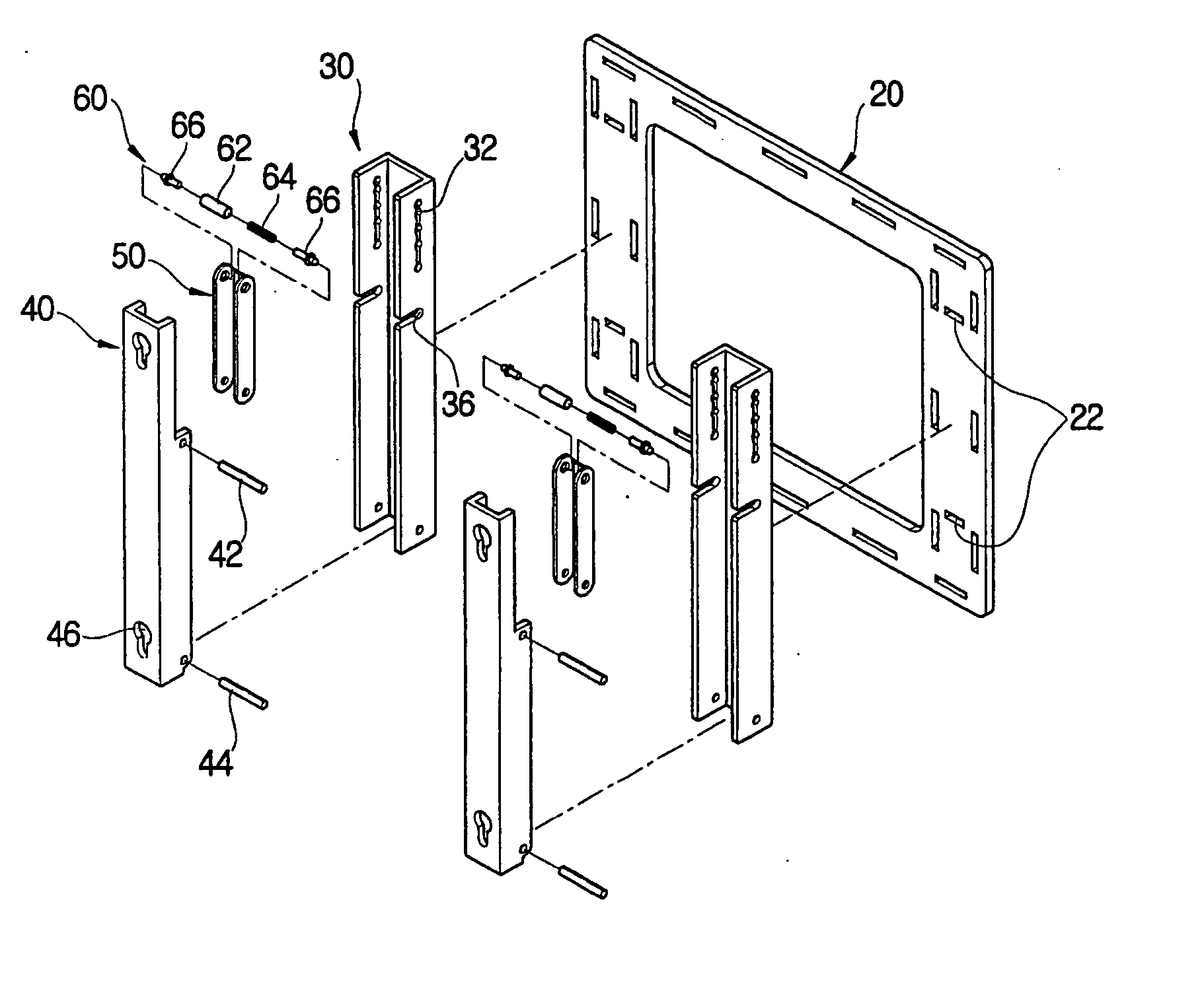
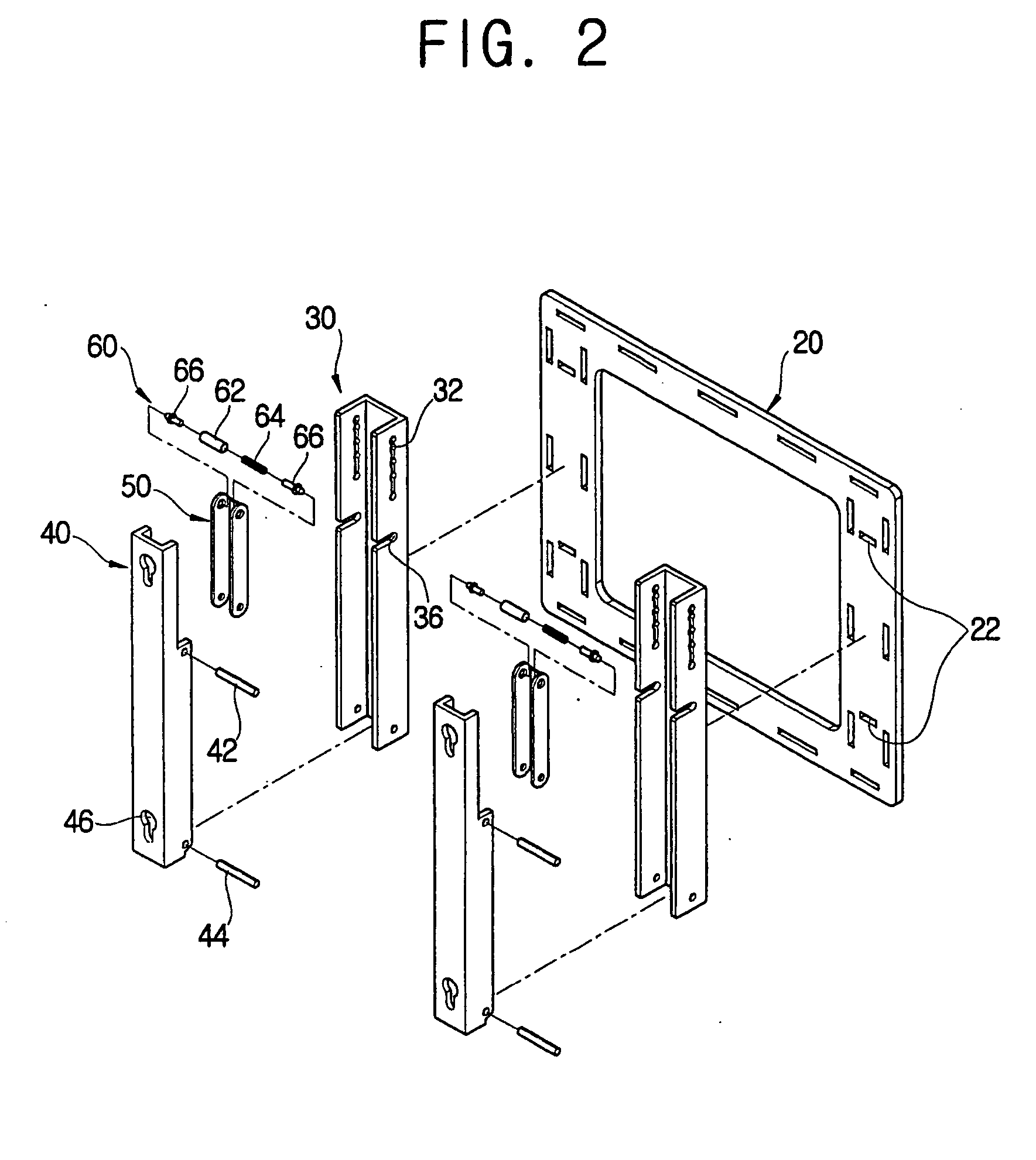
[0024]FIGS. 2 and 3 illustrate a wall mount for a display apparatus comprising two mounting brackets 30 combined with two tilting brackets 40. However, it is understood by those skilled in the art that the number of mounting brackets 50 and tilting brackets 40 may vary without departing from the principles of the invention. For example, one or more than two mounting brackets 50 and tilting brackets 40 may be used.

[0025]FIG. 2 is an exploded perspective view of a wall mount for a display apparatus, FIG. 3 is a combined perspective view of FIG. 2, FIG. 4 is a partial front sectional view of combination of plunger units of a wall mount for a display apparatus, and FIG. 5 i...


PUM


Abstract

A wall mount for a display apparatus includes a base plate mounted on a wall; a mounting bracket combined to the base plate, and having an angle control part providing a plurality of tilting angles for the display apparatus; a tilting bracket rotatably combined to a lower part of the mounting bracket, and on which the display apparatus is mounted; a connection link connecting the mounting bracket and the tilting bracket; and a plunger unit combined to the connection link and elastically combined to the angle control part, and selectively adjusting a tilting angle of the tilting bracket with respect to the mounting bracket by sliding up and down through the angle control part. The wall mount for a display apparatus is capable of supporting the display apparatus stably and adjusting a tilting angle thereof promptly and readily.

Description

CROSS-REFERENCE TO RELATED APPLICATIONS [0001] This application claims the benefit of Korean Patent Application No. 2003-64800, filed on Sep. 18, 2003, in the Korean Intellectual Property Office, the disclosure of which is incorporated herein by reference.BACKGROUND OF THE INVENTION [0002] 1. Field of the Invention [0003] The present invention relates to a wall mount, and more particularly, a wall mount for a display apparatus which can selectively adjust a tilting angle of a screen of a flat display apparatus mounted on a wall. [0004] 2. Description of the Related Art [0005] A PDP (Plasma Display Panel) or an LCD (Liquid Crystal Display) has excellent image quality and other features and thus is widely used for a TV and a monitor as a flat display apparatus. Therefore, a wall-mountable display apparatus is in demand because it comparatively reduces a limit to an installation space for the wall-mountable display apparatus. [0006] In FIG, 1, a conventional wall mount for a display ap...

Claims


Application Information

Patent Timeline
IPC IPC(8): F16M11/10H04N5/655F16M13/02
CPCF16M11/10Y10S248/923F16M2200/024F16M13/02H04N5/655
Inventor KIM, GWANG-SOO
Owner SAMSUNG ELECTRONICS CO LTD
Features
  • Generate Ideas
  • Intellectual Property
  • Life Sciences
  • Materials
  • Tech Scout
  • Unparalleled Data Quality
  • Higher Quality Content
  • 60% Fewer Hallucinations
Learn More