Method of transmitter oriented link flow control

a transmitter-oriented, flow-control technology, applied in the field of transmitter-oriented link flow control, can solve the problems of reduced switch integrated circuit die size, reduced price, and network link operating at less than full efficiency

Inactive Publication Date: 2005-03-24
EMERSON NETWORK POWER EMBEDDED COMPUTING
View PDF18 Cites 24 Cited by
  • Summary
  • Abstract
  • Description
  • Claims
  • Application Information

AI Technical Summary

Problems solved by technology

This can happen if nodes are not provisioned with enough packet buffering memory or if the nodes are not generating link flow control updates often enough or soon enough.
This can result in network links operating at less than full efficiency.
Since packet buffering memory is a major consumer of real estate in switch integrated circuits, reducing the amount of packet buffering memory will result in smaller switch integrated circuit die sizes, and consequently lower prices.

Method used


Image

  • Method of transmitter oriented link flow control
  • Method of transmitter oriented link flow control
  • Method of transmitter oriented link flow control

Examples


Embodiment Construction

[0014] In the following detailed description of exemplary embodiments of the invention, reference is made to the accompanying drawings, which illustrate specific exemplary embodiments in which the invention may be practiced. These embodiments are described in sufficient detail to enable those skilled in the art to practice the invention, but other embodiments may be utilized and logical, mechanical, electrical and other changes may be made without departing from the scope of the present invention. The following detailed description is, therefore, not to be taken in a limiting sense, and the scope of the present invention is defined only by the appended claims.

[0015] In the following description, numerous specific details are set forth to provide a thorough understanding of the invention. However, it is understood that the invention may be practiced without these specific details. In other instances, well-known circuits, structures and techniques have not been shown in detail in ord...


PUM


Abstract

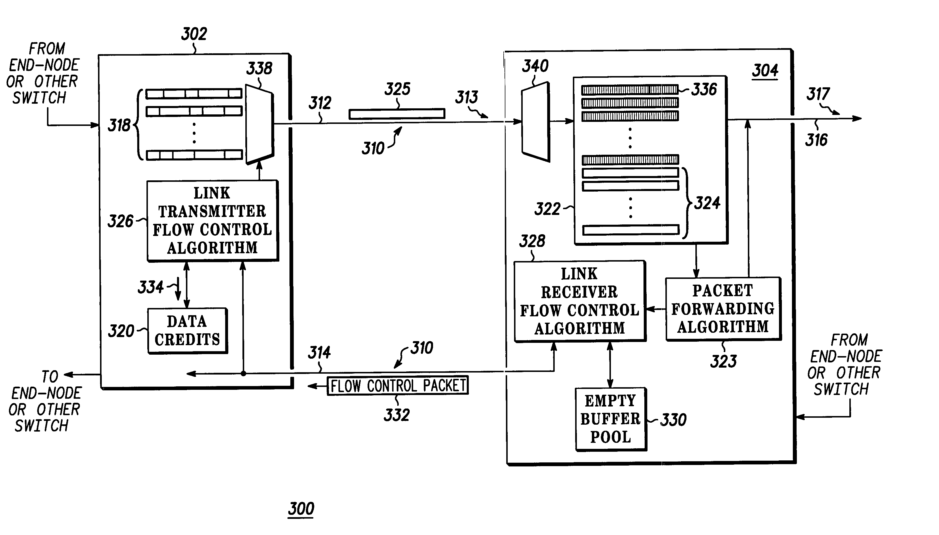
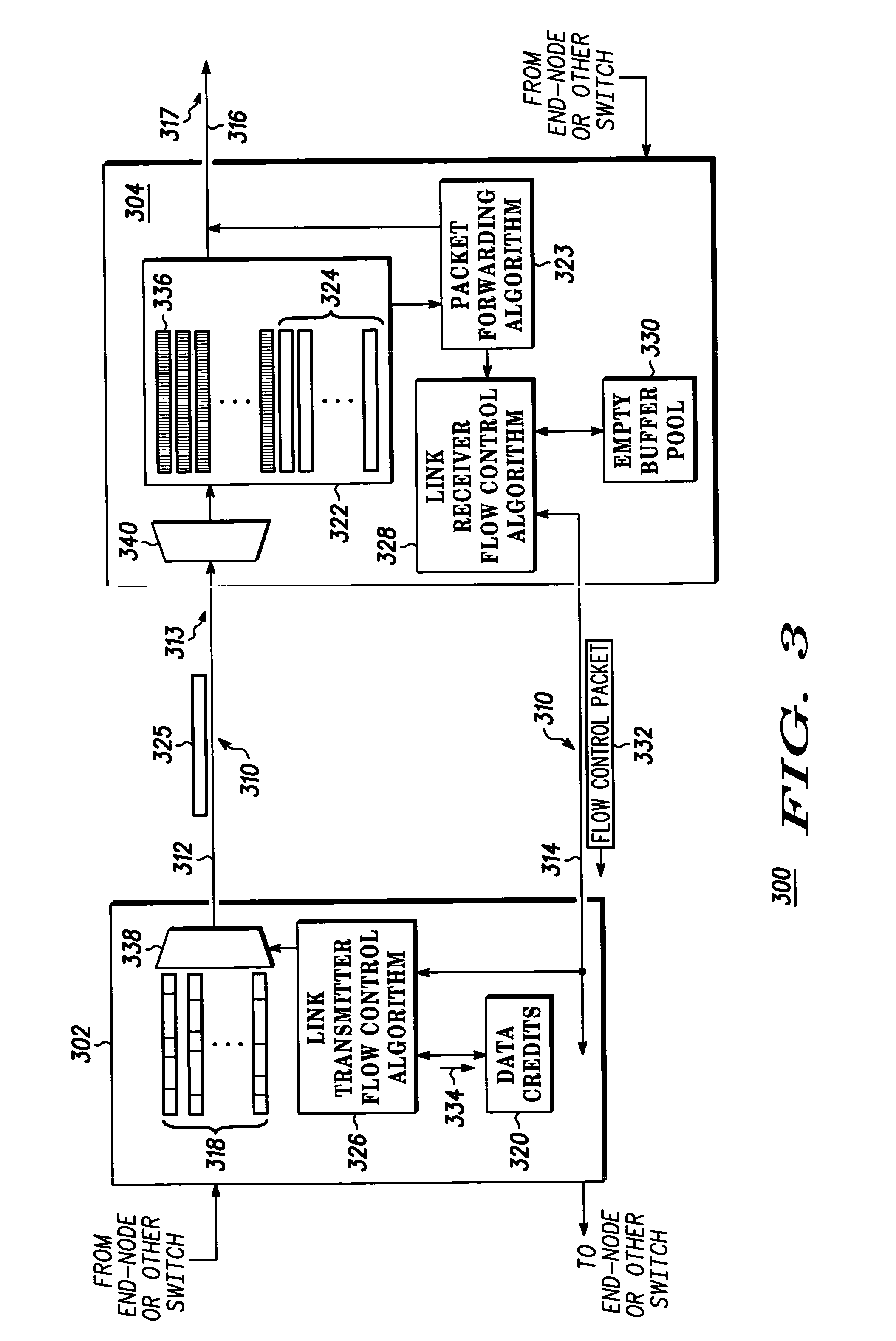
A method includes a link receiver (304) providing a plurality of data credits (320) to a link transmitter (302) and the link transmitter transmitting a packet (325) to the link receiver, where the link transmitter takes the packet from one of a plurality of logical channels (318), and where the link transmitter selects from which of the plurality of channels to draw the packet. The link receiver transmits a flow control packet (332) to the link transmitter to add additional data credits (334) to the plurality of data credits, where the link transmitter selects to which of the plurality of logical channels to allocate the additional data credits. A plurality of receiver buffers (322) are placed into a free buffer pool (330) as the packet is transmitting out of the plurality of receiver buffers, where the free buffer pool corresponds to additional data credits. The link receiver transmitting the flow control packet to the link transmitter on the reverse link (314) if the free buffer pool contains additional data credits and the reverse link is idle.

Description

RELATED CASES [0001] Related subject matter is disclosed in U.S. patent application entitled “METHOD OF EARLY BUFFER RETURN” having application no. ______ and filed on the same date herewith and assigned to the same assignee. [0002] Related subject matter is disclosed in U.S. patent application entitled “METHOD OF UPDATING FLOW CONTROL WHILE REVERSE LINK IS IDLE” having application no. ______ and filed on the same date herewith and assigned to the same assignee.BACKGROUND OF THE INVENTION [0003] As a link flow control scheme regulates the flow of traffic in a network, it can also limit the utilization of the links to less than 100%. This can happen if nodes are not provisioned with enough packet buffering memory or if the nodes are not generating link flow control updates often enough or soon enough. [0004] Link flow control protocols implemented in today's commercial integrated circuits perform sub-optimally in real-world networks. This can result in network links operating at less...

Claims


Application Information

Patent Timeline
Patent Type & Authority Applications(United States)
IPC IPC(8): H04J3/14H04L12/28H04L12/56
CPCH04L47/39H04L47/10
Inventor WISE, JEFFREY L.HAUSER, STEPHEN A.
Owner EMERSON NETWORK POWER EMBEDDED COMPUTING
Why Eureka
Try Eureka