Input key and input apparatus

a technology of input keys and input apparatus, which is applied in the field of input keys, can solve the problems of difficult to gain a click feeling upon a push of the key, difficult to perform the key operation by so-called touch typing, and difficult for the user to catch the symbol input confirmation sound or the like, so as to improve the ease and certainty of user operation, and reduce the number of operations.

Inactive Publication Date: 2005-03-24
NTT DOCOMO INC
View PDF9 Cites 41 Cited by
  • Summary
  • Abstract
  • Description
  • Claims
  • Application Information

AI Technical Summary

Benefits of technology

[0015] The present invention has been accomplished in order to solve the problems as described above, and an object of the invention is to provide an input key and input apparatus capable of reducing the number of operations on an input key in input of symbols and permitting the user to designate a symbol to be inputted, by a simpler operation.
[0044] As detailed above, the present invention succeeded in reducing the number of operations on the input key in symbol input and permitting the user to designate a symbol to be inputted, by a simpler operation.

Problems solved by technology

However, since the input apparatus described in the aforementioned Japanese Patent Application Laid-Open No. 2003-15808 is sort of a virtual keyboard, it is difficult to gain a click feeling upon a push of a key.
Since a fingertip does not sense the shape of the key top, it is also difficult to perform the key operation by so-called touch typing.
In noisy environments with traffic or the like, it is hard for the user to catch the symbol input confirmation sound or the like.
Furthermore, there are also conceivable cases where use is hardly possible at places where the generation of sound is regulated.
Incidentally, in the case of the compact electronics devices like the portable terminals, the user has to hold the cell phone by some fingers, and thus use of all the fingers for input of symbols will lead to considerable difficulties.
If this symbol input by one finger were implemented in the configuration as described in the aforementioned Japanese Patent Application Laid-Open No. 2003-15805, the same finger would have to move back and forth between the number buttons and the direction button spaced from each other, and it must be a cumbersome work.

Method used


Image

  • Input key and input apparatus
  • Input key and input apparatus
  • Input key and input apparatus

Examples


first embodiment

[0096] (First Embodiment)

[0097] The present embodiment will describe a keyboard input apparatus (hereinafter referred to as “input apparatus”) 100 provided in a portable terminal. This input apparatus 100 has a plurality of input keys 10 and is applied to mobile communication terminal equipment such as cell phones, and to portable electronics equipment such as PDA (Personal Digital Assistant).

[0098] (Overall Configuration of Input Apparatus)

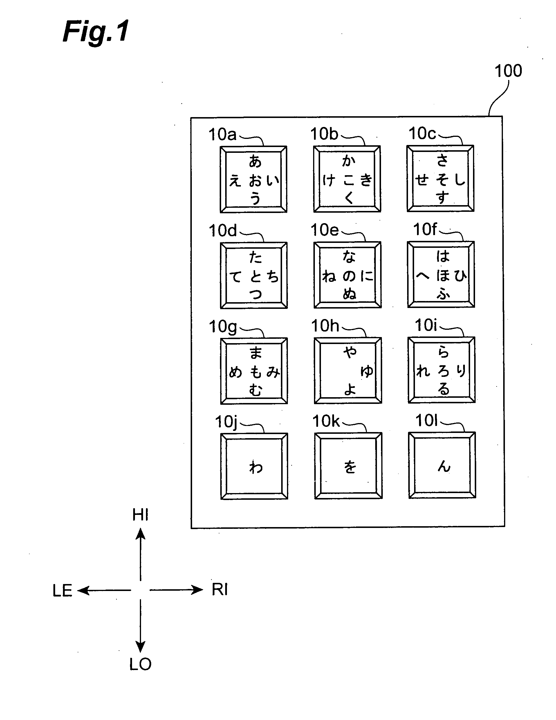
[0099]FIG. 1 is a plan view showing the appearance of input apparatus 100 according to the present embodiment. The input apparatus 100 has a plurality of input keys 10; in FIG. 1, it has a total of twelve input keys 10 (10a, 10b, 10c, . . . , 10l) in an array of four horizontal rows and three vertical columns like dial buttons of ordinary cell phones. Supposing the input apparatus 100 is an input apparatus of a cell phone, the input keys 10 should originally be assigned indications of “1”, “2”, “*”, “0”, “#”, etc., but FIG. 1 is depicted withou...

second embodiment

[0176] (Second Embodiment)

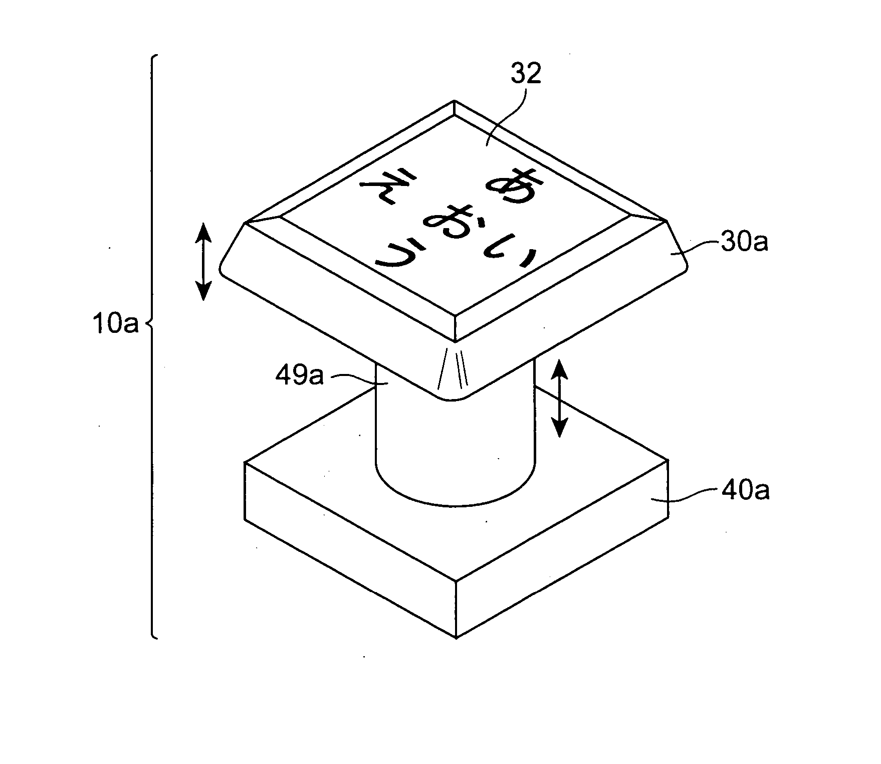
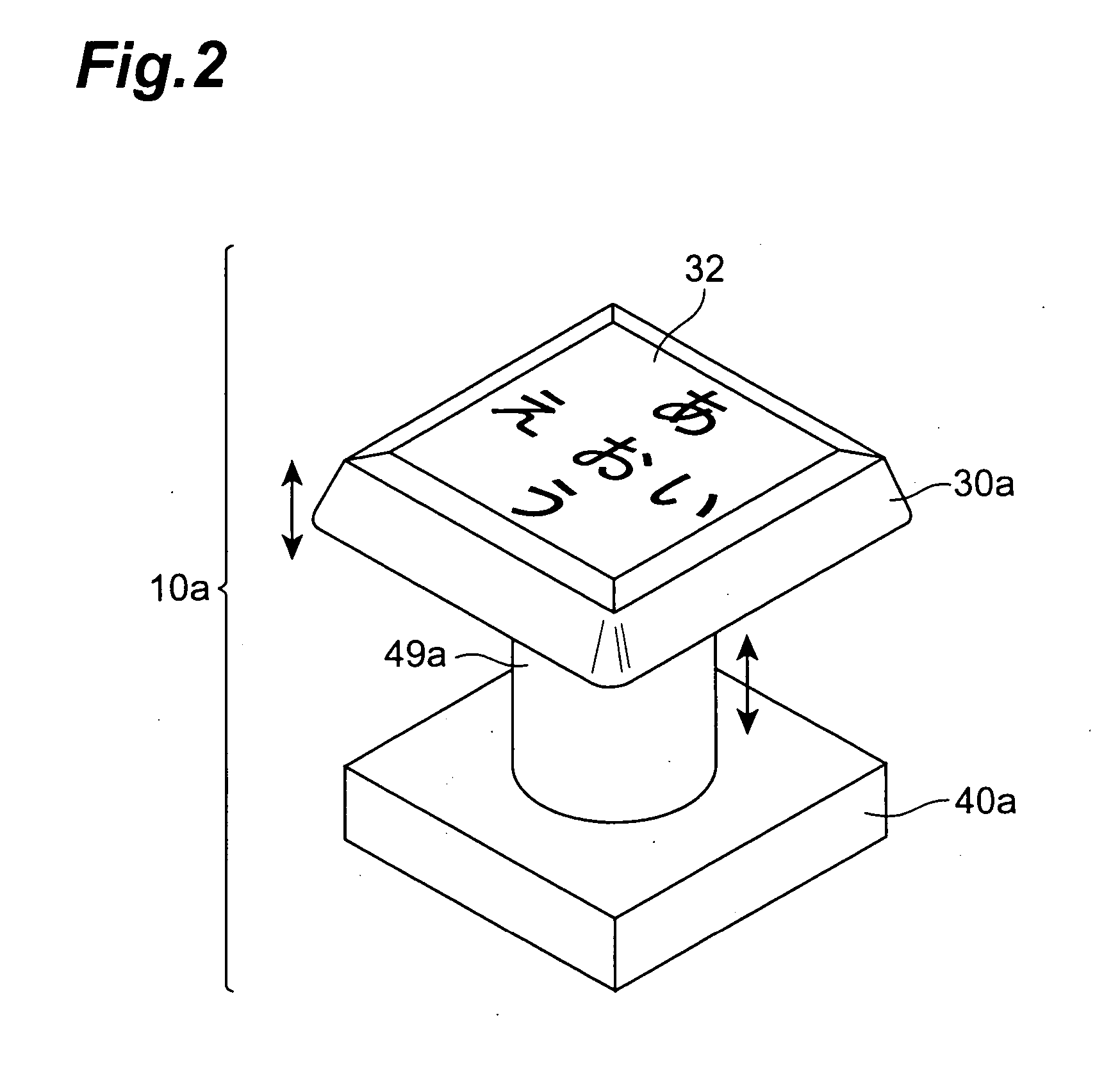
[0177] In the first embodiment, the touch pad was used as the sensor part 32 used in detection of the moving direction. This sensor part 32 can be realized by use of the principle of an optical mouse. Here the optical mouse is a mouse provided with a light emitting means and a. light receiving means on the back side of the mouse. This configuration is able to detect a direction of movement of a contact surface with the mouse relative to the mouse and relatively detect a direction and an amount of movement of the mouse itself.

[0178] A moving direction of a finger can be detected by inverting the optical mouse upside down (or turning it over) from the usual use form and bringing a finger in touch with the light emitting means. The sensor part 32 in the present embodiment can be realized by applying the same configuration to the input keys.

[0179] The technology of optically detecting the finger movement in this manner is described, for example, in Japanese P...

third embodiment

[0197] (Third Embodiment)

[0198] In the first embodiment the converter 50 was provided with the conversion tables 51 for the respective input keys 10. The conversion tables 51 can be preliminarily set in production stages, but they may also be arranged to be freely set by the user. For implementing this setting, a conceivable configuration is such that an external setting device is connected to the converter 50 and the contents of the conversion tables 51 provided inside the converter 50 are rewritten by use of this setting device.

[0199] In this case, it would be convenient to allow the user to rewrite the contents of the conversion tables 51 through manipulation and input with the input keys 10. The present embodiment will describe an embodiment where the user rewrites the contents of the conversion tables 51, using the input keys 10 as described above.

[0200]FIG. 7 is an illustration showing an appearance configuration of a cell phone 300 equipped with an input apparatus 200 accor...


PUM


Abstract

An object of the present invention is to provide an input apparatus and input key capable of reducing the number of operations on the input key for input of symbols and permitting a user to designate a symbol to be inputted, by a simpler operation. An input key 10a to which a plurality of symbols or marks are assigned, has a key top 30a to be pushed, a sensor part 32 for detecting a push position on a surface of the key top 30 by a finger or the like used to push the key top 30a, a moving direction detector 34 for detecting a change of the push position of the finger or the like detected by the sensor part 32 and for detecting a moving direction of the finger or the like during movement thereof on the surface of the key top 30, and a switch 40a to change a state with a push on the key top 30, and has a converter 50 for converting a state of the switch 40a and the moving direction detected by the moving direction detector 34, into symbol information.

Description

BACKGROUND OF THE INVENTION [0001] 1. Field of the Invention [0002] The present invention relates to an input key to which a plurality of input information elements are assigned, and an input apparatus for inputting information by the input key. [0003] 2. Related Background Art [0004] A portable terminal such as a cell phone needs to be compact enough for a user to carry. For this reason, where a cell phone is provided with a keyboard, the number of input keys in the keyboard is often much smaller than that in a so-called full keyboard. [0005] In the portable terminals, therefore, it is common practice to assign an input key a plurality of symbols and designate a symbol to be inputted, by the number of pushes on one input key. For example, one push on a key results in inputting “” in Japanese, and two pushes result in inputting “” in Japanese. [0006] By adopting the technique of this type, it is feasible to input numerous symbols, such as Japanese hiragana writing symbols and kataka...

Claims


Application Information

Patent Timeline
Patent Type & Authority Applications(United States)
IPC IPC(8): B41J5/08G06F1/16G06F3/02G06F3/023H01H9/16H01H13/00H01H36/00H01H89/00H03M11/04H03M11/22H04B1/38H04M1/23H04M1/247
CPCG06F1/1626G06F1/1662G06F3/0202G06F3/0234H04M1/233H01H2217/032H01H2239/078H04M1/23H01H2003/0293H04B1/38
Inventor SUGIMURA, TOSHIAKIFUKUMOTO, MASAAKI
Owner NTT DOCOMO INC
Why Eureka
Try Eureka