Speedometer controller and speedometer control method
- Summary
- Abstract
- Description
- Claims
- Application Information
AI Technical Summary
Benefits of technology
Problems solved by technology
Method used
Image
Examples
first embodiment
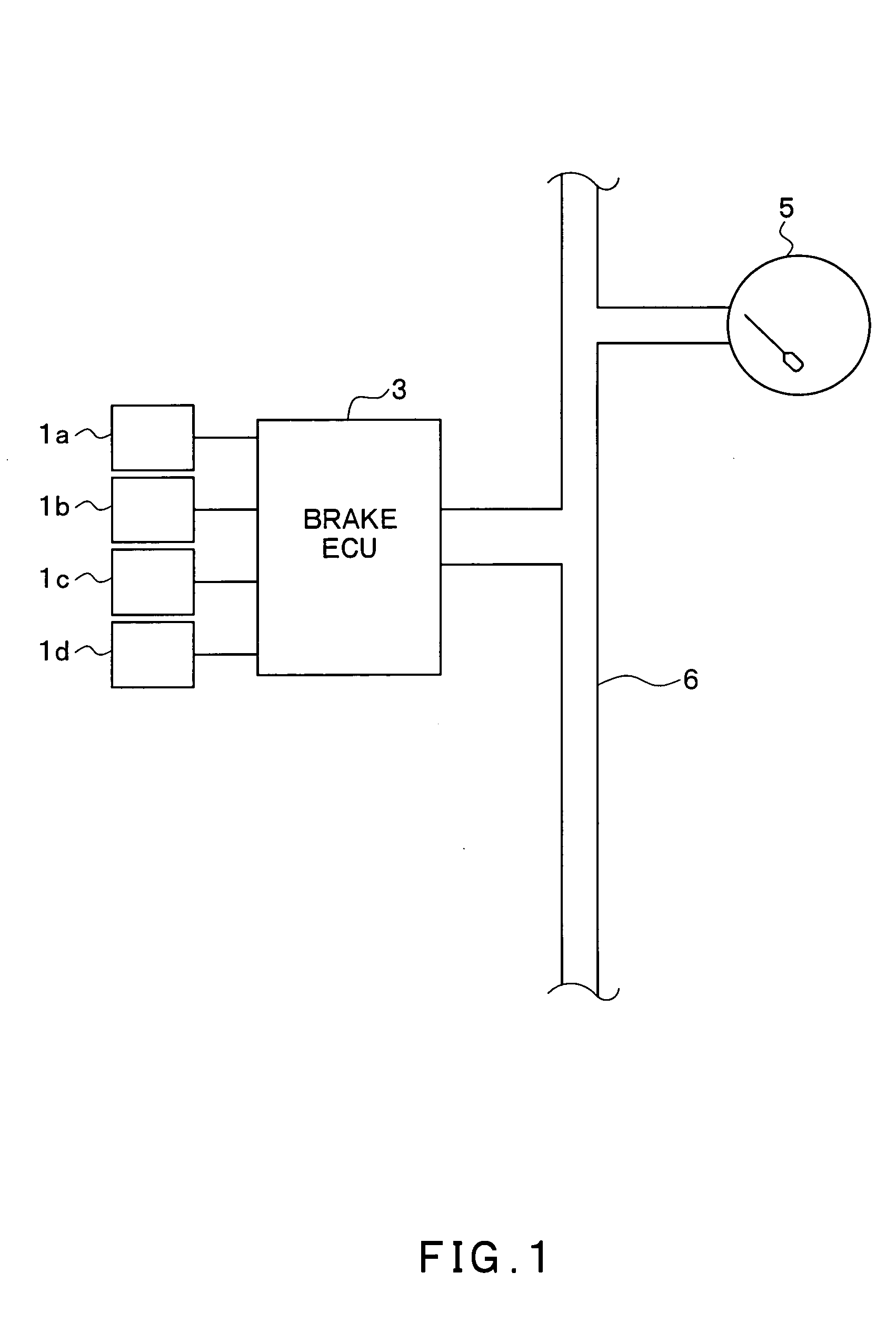
[0024]FIG. 1 shows a block diagram of a speedometer control system as an application of the first embodiment. The speedometer control system of the first embodiment is described with reference to the drawings.
[0025] The speedometer control system has a structure including wheel speed sensors 1a-1d provided on a vehicle, a brake ECU 3 for an ABS control and a traction control for driving an ABS actuator, a speedometer 5 and a serial communication line 6 for connecting these structural components.
[0026] The wheel speed sensors 1a to 1d are provided respectively on the wheels, not shown, of a vehicle and the wheel speed sensors 1a to 1d are provided respectively on the wheels of the vehicle, and output pulse signals that become vehicle wheel speed signals of the corresponding wheels. The vehicle wheel speed signals are used in, for example, a vehicle wheel speed calculation of the respective wheels, a vehicle body speed calculation and a slip ratio calculation.
[0027] The brake ECU 3...
PUM
 Abstract
Description
Claims
Application Information
 - R&D
- Intellectual Property
- Life Sciences
- Materials
- Tech Scout
- Unparalleled Data Quality
- Higher Quality Content
- 60% Fewer Hallucinations
Browse by: Latest US Patents, China's latest patents, Technical Efficacy Thesaurus, Application Domain, Technology Topic, Popular Technical Reports.
© 2025 PatSnap. All rights reserved.Legal|Privacy policy|Modern Slavery Act Transparency Statement|Sitemap|About US| Contact US: help@patsnap.com


