
Speedometer controller and speedometer control method

a technology of speedometer and control method, which is applied in the field of speedometer, can solve the problems of changing the vehicle speed, and the detection signal of the wheel speed sensor cannot obtain the correct vehicle speed

Inactive Publication Date: 2007-02-06
ADVICS CO LTD
View PDF8 Cites 10 Cited by
  • Summary
  • Abstract
  • Description
  • Claims
  • Application Information

AI Technical Summary

Benefits of technology

This approach prevents abrupt changes in the speedometer display, reducing driver discomfort by gradually shifting from one calculation method to another, even when differences between calculated speeds are significant.

Problems solved by technology

In a case where the front and rear wheels have different diameters and where the detection signals from the wheel speed sensor on the rear wheels that are used in the vehicle speed calculation are thought to be unreliable, for example, when a normal tire has been replaced with a spare, a correct vehicle speed cannot be obtained from the detection signals from the wheel speed sensor.
Thus the correct vehicle speed cannot be obtained from the wheel speed sensor.
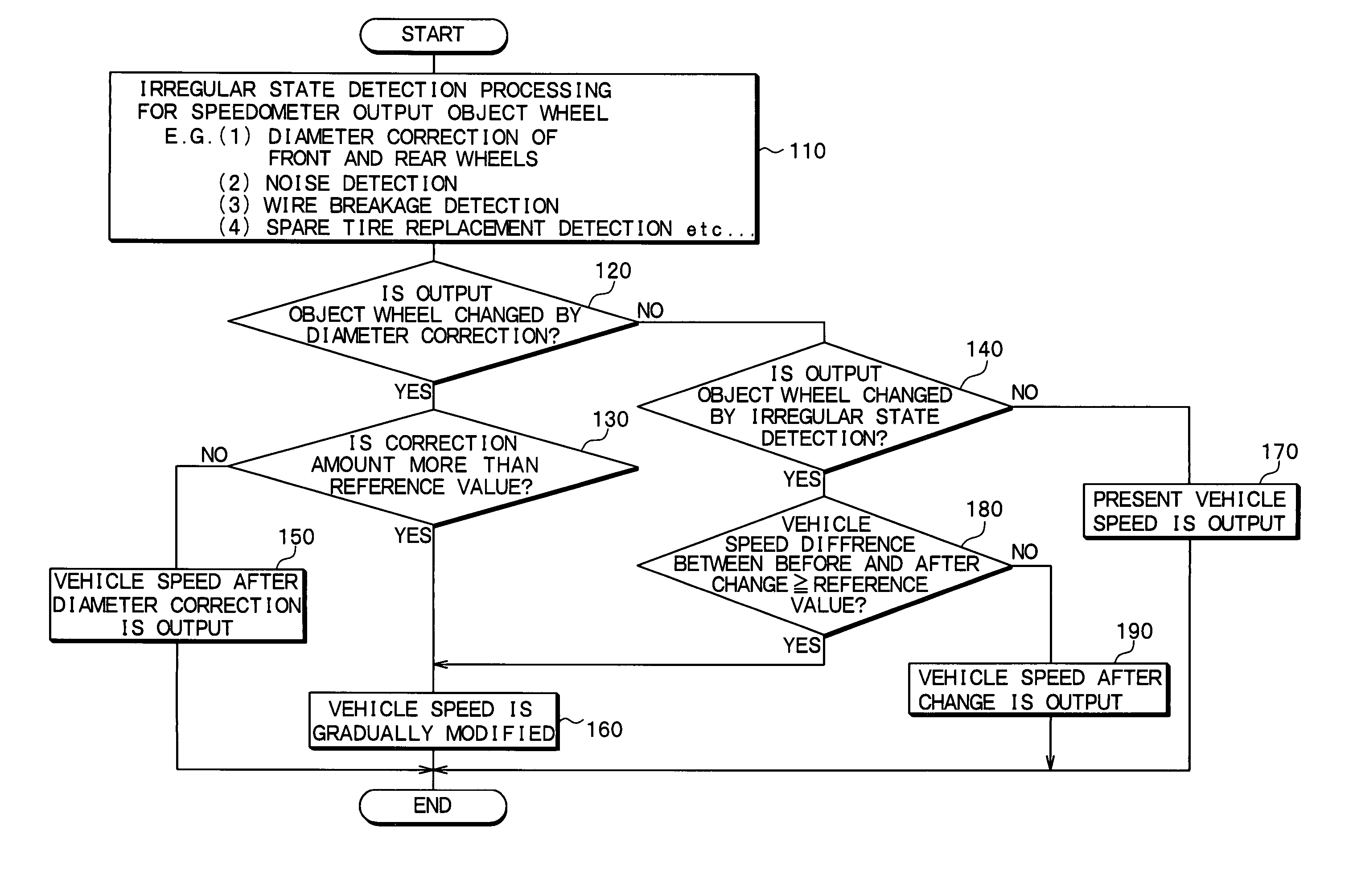
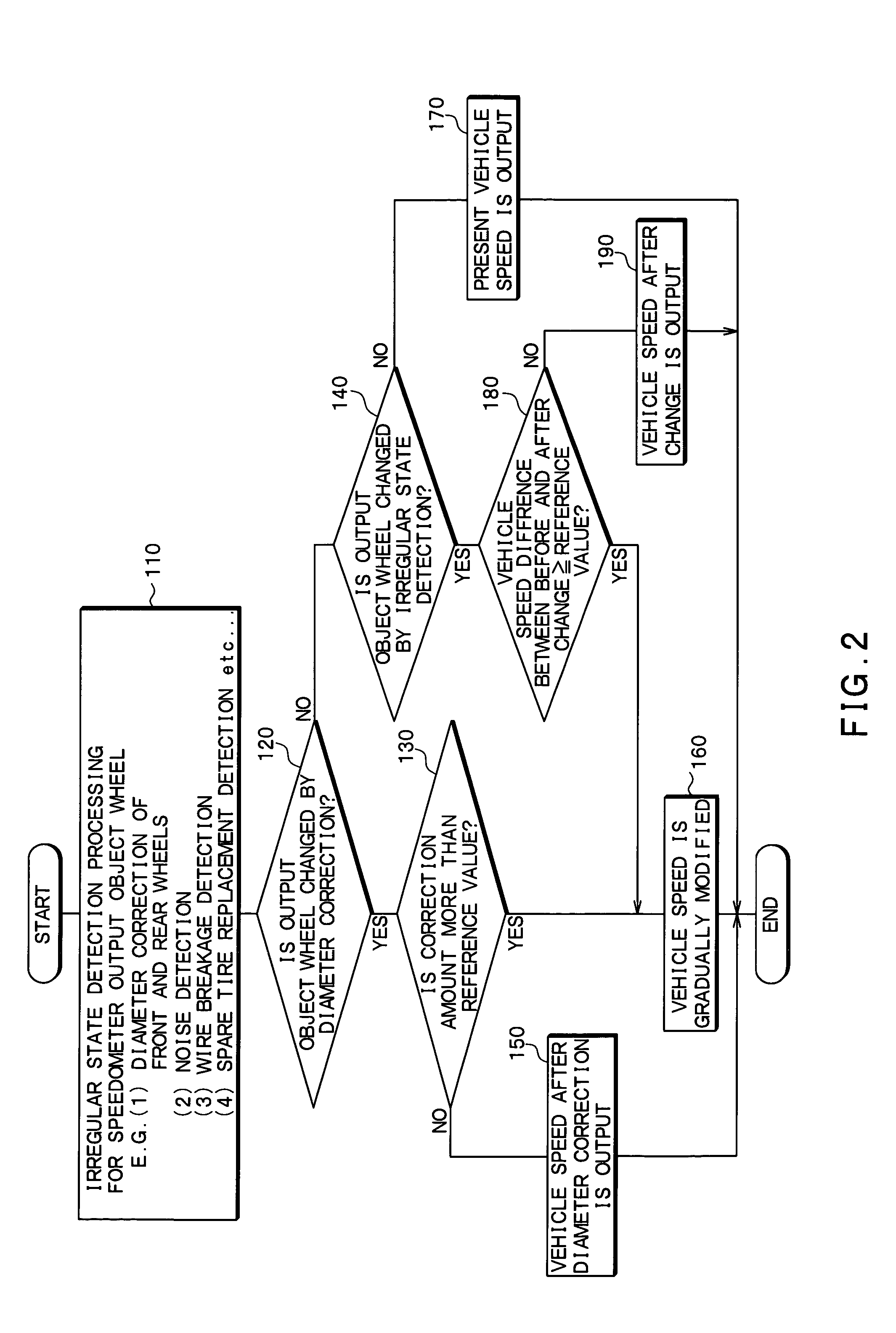
This will cause a change in the vehicle speed before and after the diameter correction and, in a case where the speedometer display changes abruptly, the driver will be caused to feel discomfort.
However, in this case, an abrupt change in the speedometer display may cause the driver to feel discomfort if the newly obtained vehicle speed is different from the previous vehicle speed.

Method used


Image

  • Speedometer controller and speedometer control method
  • Speedometer controller and speedometer control method
  • Speedometer controller and speedometer control method

Examples


first embodiment

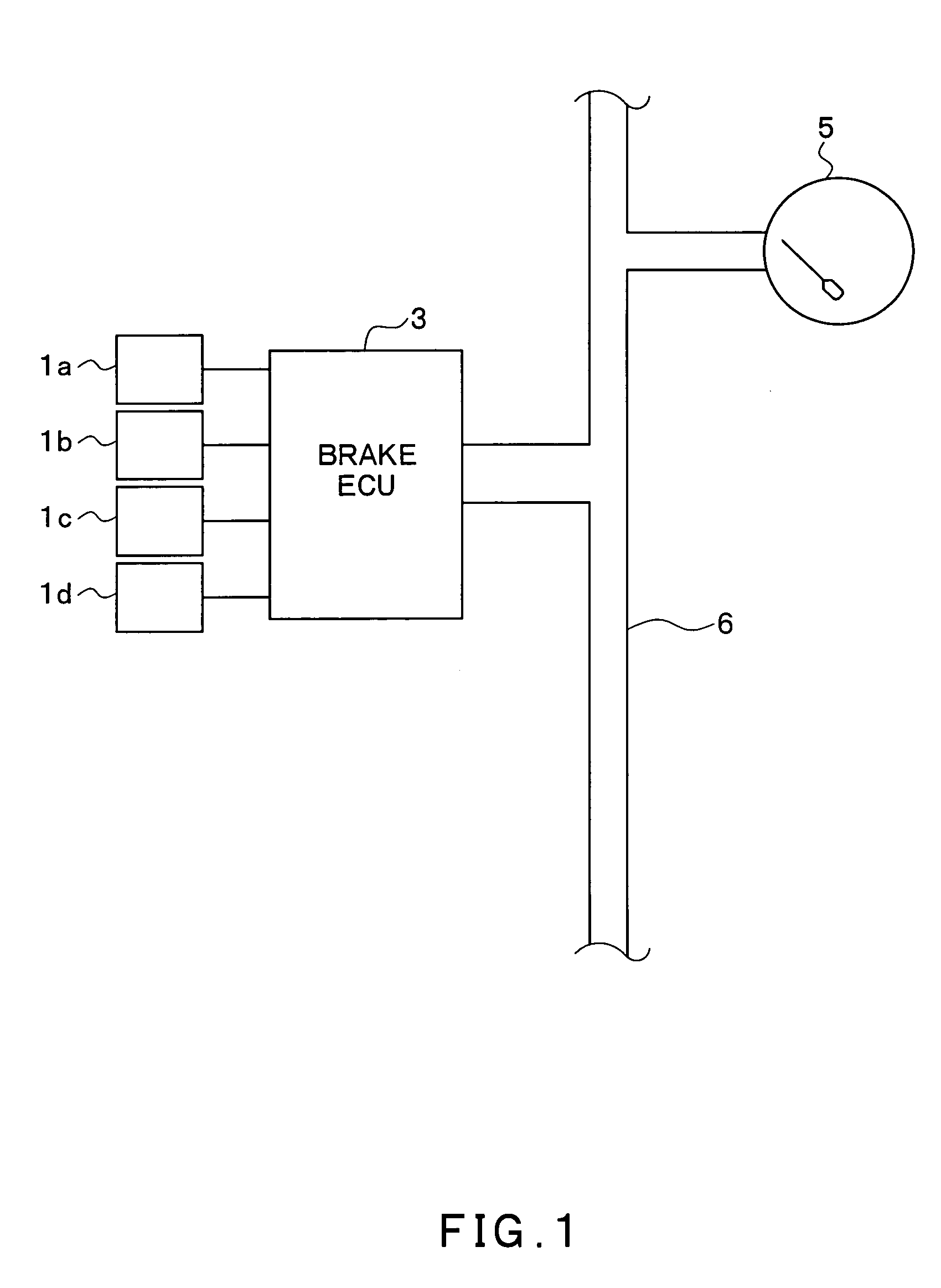
[0024]FIG. 1 shows a block diagram of a speedometer control system as an application of the first embodiment. The speedometer control system of the first embodiment is described with reference to the drawings.

[0025]The speedometer control system has a structure including wheel speed sensors 1a–1d provided on a vehicle, a brake ECU 3 for an ABS control and a traction control for driving an ABS actuator, a speedometer 5 and a serial communication line 6 for connecting these structural components.

[0026]The wheel speed sensors 1a to 1d are provided respectively on the wheels, not shown, of a vehicle and the wheel speed sensors 1a to 1d are provided respectively on the wheels of the vehicle, and output pulse signals that become vehicle wheel speed signals of the corresponding wheels. The vehicle wheel speed signals are used in, for example, a vehicle wheel speed calculation of the respective wheels, a vehicle body speed calculation and a slip ratio calculation.

[0027]The brake ECU 3 corre...


PUM


Abstract

A vehicle speed is obtained from detection signals obtained from wheel speed sensors. In a case where a vehicle speed calculation is shifted from a first method to a second method, a vehicle speed displayed on a speedometer is gradually changed from the vehicle speed obtained by the first method to the vehicle speed obtained by the second method. This avoids abrupt change in the displayed vehicle speed causing the driver to feel discomfort.

Description

CROSS REFERENCE TO RELATED APPLICATION[0001]This application is based upon and claims the benefit of Japanese Patent Application No. 2003-331483 filed on Sep. 24, 2003, the content of which are incorporated herein by reference.FIELD OF THE INVENTION[0002]The present invention relates to a speedometer controller that obtains a vehicle speed based on detection signals from wheel speed sensors and a speedometer control method thereof.BACKGROUND OF THE INVENTION[0003]Related art is known in which a vehicle speed is obtained based on detection signals from wheel speed sensors and then displayed on a speedometer (refer to Japanese Laid-open Patent Publication No. HEI 8-268252). In the case where front and rear wheels have different diameters, the vehicle speed is calculated based on detection signals from either the front wheel or the rear wheel. For example, in a case of a rear wheel drive vehicle, the rear wheels are the object of vehicle speed calculation and the vehicle speed is obtai...

Claims


Application Information

Patent Timeline
Patent Type & Authority Patents(United States)
IPC IPC(8): G01P7/00G01P11/00G01D11/00B60K35/00B60T8/172B60T8/32B60T8/66G01P1/07G01P3/00G01P21/02G06F17/00
CPCB60T8/172G01P1/07B60T2250/04
Inventor TSURUHARA, RYUZOINOUE, YASUMI
Owner ADVICS CO LTD
Learn More