Systems and methods for configuring a warehouse for tracking the location of items within a controlled area

a warehouse and controlled area technology, applied in the field of tracking using radio frequency identification tags, can solve the problems of reducing affecting the accuracy of location estimation, and requiring equipment for measuring speed, direction, and other motion parameters,

Inactive Publication Date: 2005-03-24
SINGLE CHIPS SYST
View PDF6 Cites 72 Cited by
  • Summary
  • Abstract
  • Description
  • Claims
  • Application Information

AI Technical Summary

Benefits of technology

[0011] A location tracking system for tracking the location of items within a controlled area comprises a plurality of RFID tags located according to the required accuracy of the location determinations. Vehicles configured to transport items being tracked can then comprise two RFID interrogators configured to acquire RFID information from the plurality of RFID tags and transmit the RFID tag information to a location authority. The separation the two RFID interrogators can be set based on the spacing of the plurality of RFID tags such that the required accuracy results. The location authority can then simply map the RFID tag information to coordinate information stored for each of the plurality of tags to obtain the location of the vehicle and, therefore, the item being transported.

Problems solved by technology

The estimation will, however, necessarily comprise errors.
The problem with the approach described in relation to FIG. 1 is that the equipment for measuring speed, direction, and other motion parameters can be very costly to equip on all forklifts in a warehouse.
Further, if a forklift 110 moves for a prolonged period within an area 150 without coming into range of an RFID tag 102, errors in the location estimation will accumulate reducing the accuracy of location estimations.

Method used


Image

  • Systems and methods for configuring a warehouse for tracking the location of items within a controlled area
  • Systems and methods for configuring a warehouse for tracking the location of items within a controlled area
  • Systems and methods for configuring a warehouse for tracking the location of items within a controlled area

Examples


Embodiment Construction

.”

BRIEF DESCRIPTION OF THE DRAWINGS

[0013] Features, aspects, and embodiments of the inventions are described in conjunction with the attached drawings, in which:

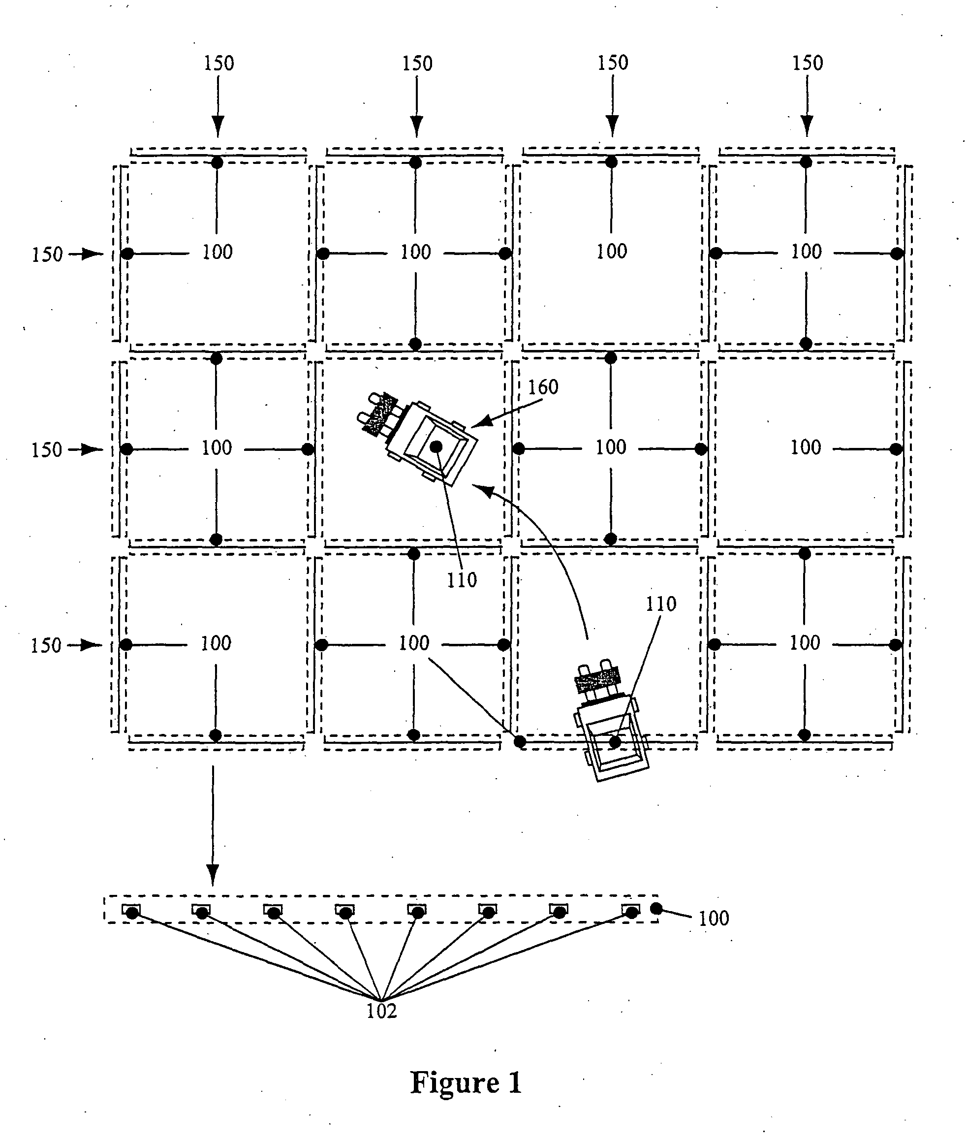
[0014]FIG. 1 is a diagram illustrating an exemplary tracking system that uses RFID tags to track the location of items within a controlled area;

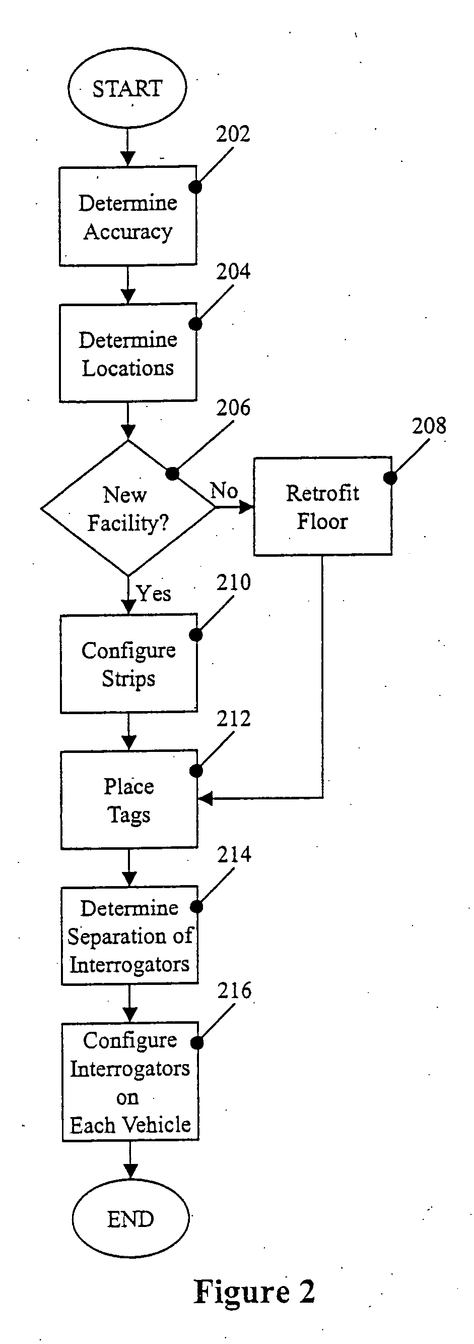
[0015]FIG. 2 is a flow chart illustrating an example method for configuring a controlled area with RFID tags for tracking the location of items within the controlled area in accordance with one embodiment of the invention;

[0016]FIG. 3 is a diagram illustrating a controlled area configured with RFID tags in accordance with the method of FIG. 2;

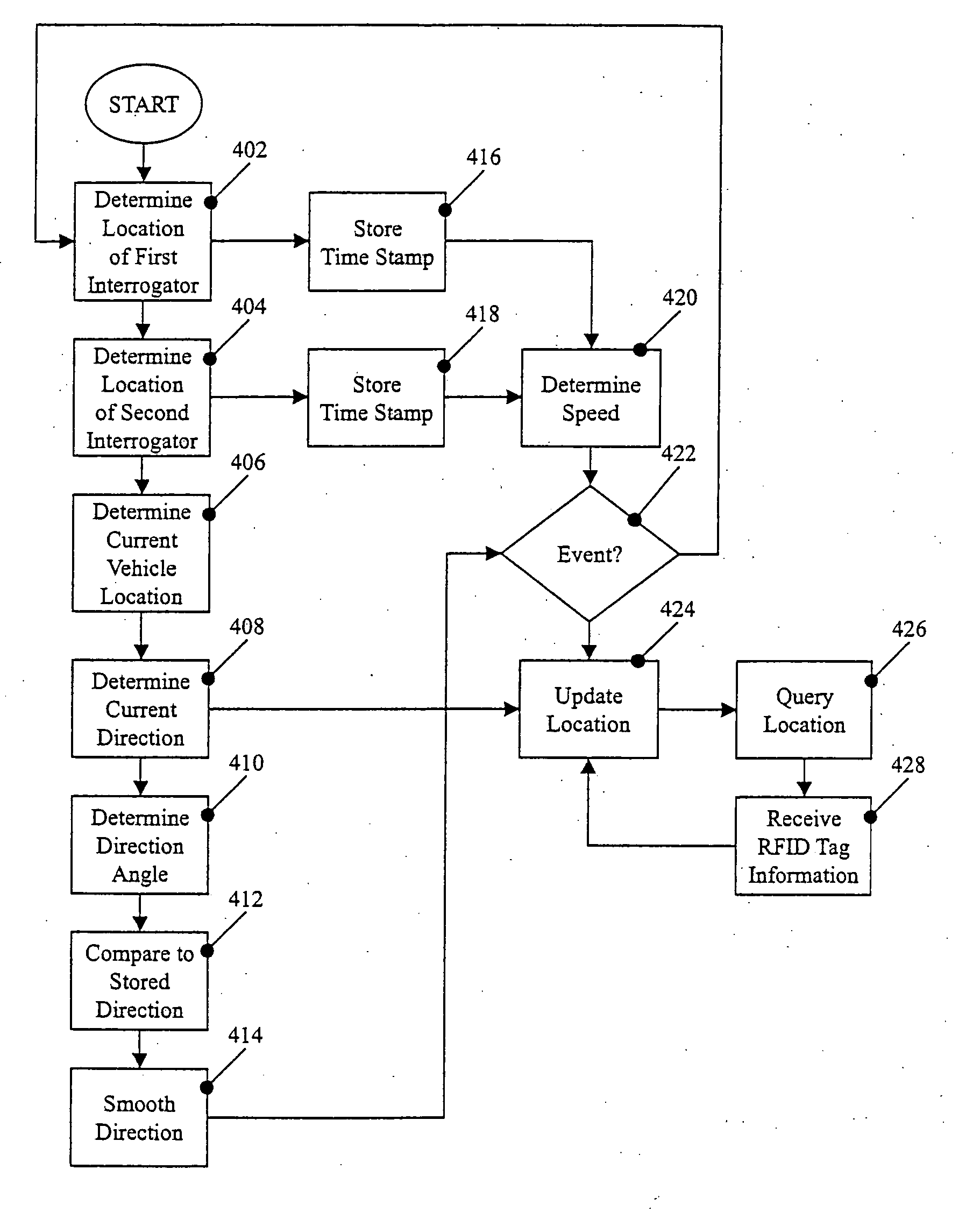
[0017]FIG. 4 is a flow chart illustrating an example process for tracking the location of an item within the controlled area of FIG. 3 in accordance with one embodiment of the invention; and

[0018]FIG. 5 is a diagram illustrating an example computer system that can comprise part of a location authority included in a tracking system configur...


PUM


Abstract

A location tracking system for tracking the location of items within a controlled area comprises a plurality of RFID tags located according to the required accuracy of the location determinations. Vehicles configured to transport items being tracked include two RFID interrogators configured to acquire RFID information from the plurality of RFID tags and to transmit the RFID tag information to a location authority. The separation the two RFID interrogators is set based on the spacing of the plurality of RFID tags such that the required accuracy results. The location authority can then simply map the RFID tag information to coordinate information stored for each of the plurality of tags to obtain the location of the vehicle and, therefore, the item being transported.

Description

RELATED APPLICATIONS INFORMATION [0001] This application is related to U.S. patent application Ser. No. TBD (Atty. Dkt. No. 38326.00005.UTL1), entitled “Systems and Methods for Tracking the Location of Items Within a Controlled Area,” filed TBD.BACKGROUND [0002] 1. Field of the Inventions [0003] The field of the invention relates generally to tracking using radio frequency identification tags and more particularly to tracking inventory on vehicles in a warehouse setting. [0004] 2. Background Information [0005] In a warehouse environment, for example, the ability to track and control inventory can be vital. To aid in tracking inventory, floor embedded RFID tags have been used to facilitate the process of locating vehicles used to move the inventory in warehouses. The embedded RFID tags provide a fixed reference point to which tracking systems can be calibrated in real-time. In such a conventional tracking system, sensors on-board the vehicle are often used to provide direction and sp...

Claims


Application Information

Patent Timeline
Patent Type & Authority Applications(United States)
IPC IPC(8): G06Q10/00
CPCG06Q10/087G06Q10/08
Inventor BANN, GARY
Owner SINGLE CHIPS SYST
Why Eureka
Try Eureka