Simulated locomotion method and apparatus

a locomotion and simulated technology, applied in the field of simulated locomotion methods and apparatus, can solve the problems of not being able to use hands for other, more normal tasks, and not being able to look and move independently, so as to reduce the footprint and overall size of the system, reduce the vertical extent of the space, and reduce the effect of system footprin

Inactive Publication Date: 2009-06-02
USA AS REPRESENTED BY THE SEC OF THE NAVY THE
View PDF32 Cites 143 Cited by
  • Summary
  • Abstract
  • Description
  • Claims
  • Application Information

AI Technical Summary

Benefits of technology

[0018]It is an advantage that the equipment needed for the apparatus is relatively compact (compared to other systems) and potentially inexpensive. The present invention, having the user seated and turning 180 degrees rather than a full 360 degrees, significantly reduces the footprint and hence the size of the training station compared to other VE systems such as those requiring the user to be standing and walking. A seated user also reduces the vertical extent of the space that needs to be tracked, further decreasing the system's footprint and overall size because the tracking or position sensors can be positioned within a more confined space.

Problems solved by technology

However, looking and moving are no longer independent, so that the user cannot turn their head to look to the side while moving without altering their path.
This makes it difficult to move to a desired position in the virtual environment.
However, the control mechanism interferes with manipulation, so that the hand cannot be used for other, more normal tasks.
Torso based steering frees the head for looking and the hands for manipulation, but it does not support sidestepping.
While a person in the real world will typically move in the direction that the front of the torso is pointing, sometimes this is not the case.
However, the tilting of the torso approach precludes the user tilting for other purposes.
The shifting of weight approach, where weight is shifted relative to the feet, is of limited use because a user cannot pace to turn.
However, when using a head-mounted display, the user easily loses track of where he stands with respect to the neutral position although the direction and rate of optical flow provides one indication of where the user is situated.
However, with the directional coordinate frame relative to a fixed external point in space, this is an unnatural condition that makes turning of the body and controlling the direction of motion even more independent than they are with natural locomotion.
This approach is also incompatible with physical locomotion because velocity is controlled by the relative position of the body.
However, use of hand controls for speed interferes with use of the fingers for manipulative tasks which are becoming more desired and common, especially in combat systems where the user needs to hold and aim a weapon.
Another disadvantage is that when head-mounted displays are used, the user cannot see his hands or how the fingers touch the buttons, limiting the number of buttons the user can deal with.
While useful, this system did not allow a user to walk in one direction and look in another direction.
However, the placement of a hoop at waist level does not allow a user to hold an object such as a rifle by their side.
However, turning while accelerating can lead to a misalignment between the user's direction of translation and the centering motion of the controller, causing a loss of balance.
Even turning in place can be difficult because the controller registers the motion and compensates for it by moving the surface under the user's feet.
Another problem is that a user can decelerate very quickly, coming to a full stop in a single pace or by redirecting their motion while walking fast.
The user normally perceives linear and angular acceleration using their vestibular system, which leads to perceptual conflicts when using this system and which thus makes its use difficult.
However, this system is disadvantageous as it does not allow use of a normal pace or gait, or of a side pace.

Method used


Image

  • Simulated locomotion method and apparatus
  • Simulated locomotion method and apparatus
  • Simulated locomotion method and apparatus

Examples


Embodiment Construction

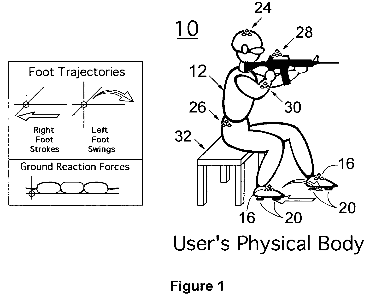
[0024]DEFINITION(S): The term “tracker” as used herein includes the following: A tracking system made up of a set of components that allow a position detector to determine one or more of the spatial coordinates (X, Y, Z, Yaw, Pitch, Roll) of one or more tracked elements (e.g., parts of the body). Many tracking systems require the attachment of one or more tracking components to the tracked element. A “sensor” is a device that registers specific forms of structured energy. Position detectors take in readings from one or more sensors to determine the coordinates of tracked elements. In the case of a conventional optical tracking system, a set of markers is attached to the element to be tracked, visible to optical sensors mounted in the room. Other tracking technologies, including acoustic and potentially RF tracking, may adopt a similar configuration. One or more emitting or reflective elements for the sensed form of transmitted energy is attached to the tracked element and sensors ar...


PUM


Abstract

An apparatus for interfacing 3D movements of a user to control the locomotion of an avatar in a virtual environment includes a position tracker for tracking the position of a user's feet, with the foot motions including swinging and stroking; a computer programmed for (i) computing a direction and extent of motion of a reference in the virtual environment based on the foot positions and (ii) providing an avatar corresponding to the computed direction and extent of motion; and a display for displaying the avatar in the virtual environment. The apparatus accordingly uses the gestural motion of the user's feet while seated to simulate natural human locomotion. The gestural motions of stroking and swinging include translational and rotating movements, and are chosen to correspond to the actions of the feet and legs during natural human locomotion, providing natural control of virtual locomotion. The apparatus is also designed for controlling the locomotion of a remote vehicle.

Description

[0001]The present application claims the benefit of the priority filing date of provisional patent application No. 60 / 603,517, filed Aug. 11, 2004, incorporated herein by reference.FIELD OF THE INVENTION[0002]The present invention relates generally to a method and apparatus for interfacing gestural 3D movements of a user to the locomotion of a reference in a virtual or remote environment. In particular, the present invention relates to such a method and apparatus where a user can simulate motion through a virtual environment while seated. The invention also relates to user control of a remote vehicle.BACKGROUND OF THE INVENTION[0003]A virtual environment is an array of sensory cues generated in response to a user's actions that gives the user the impression of dealing directly with a three dimensional model. Typically either a head mounted display or a surround screen display is used to present a dynamic perspective image of the visual environment as the user moves within it. The vi...

Claims


Application Information

Patent Timeline
Patent Type & Authority Patents(United States)
IPC IPC(8): G06T15/70
CPCG06F3/011G06T13/40
Inventor TEMPLEMAN, JAMES N.
Owner USA AS REPRESENTED BY THE SEC OF THE NAVY THE
Why Eureka
Try Eureka