
Single magnetic circuit dual output speaker

a single-circuit, dual-output technology, applied in the direction of deaf-aid sets, electrical transducers, transducer details, etc., can solve the problems of occupying more space of the speaker, generating a higher production cost, and a complicated assembly of the single-circuit dual-output speaker structure, so as to achieve better protection

Active Publication Date: 2005-03-31
MEILOON INDAL
View PDF11 Cites 19 Cited by
  • Summary
  • Abstract
  • Description
  • Claims
  • Application Information

AI Technical Summary

Benefits of technology

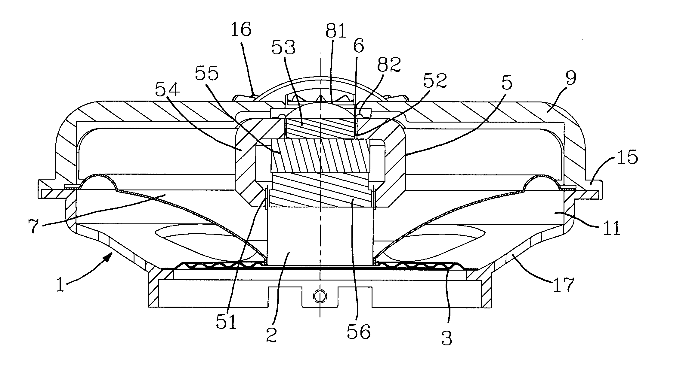
[0009] The primary objective of the present invention is to provide an improved single magnetic circuit dual output speaker adopting a bridge structure as reinforcement for the design, not only providing a better protection on the magnetic circuit, but also facilitating the holding by the bridge during the assembling and maintenance of the speaker.

Problems solved by technology

Each speaker can be applied for a single function for generating sound, and if we want to differentiate the high pitch from the low pitch, then it requires two speakers; one for the high pitch and the other for the low pitch, not only generating a higher production cost, but also occupying more spaces of the speaker.
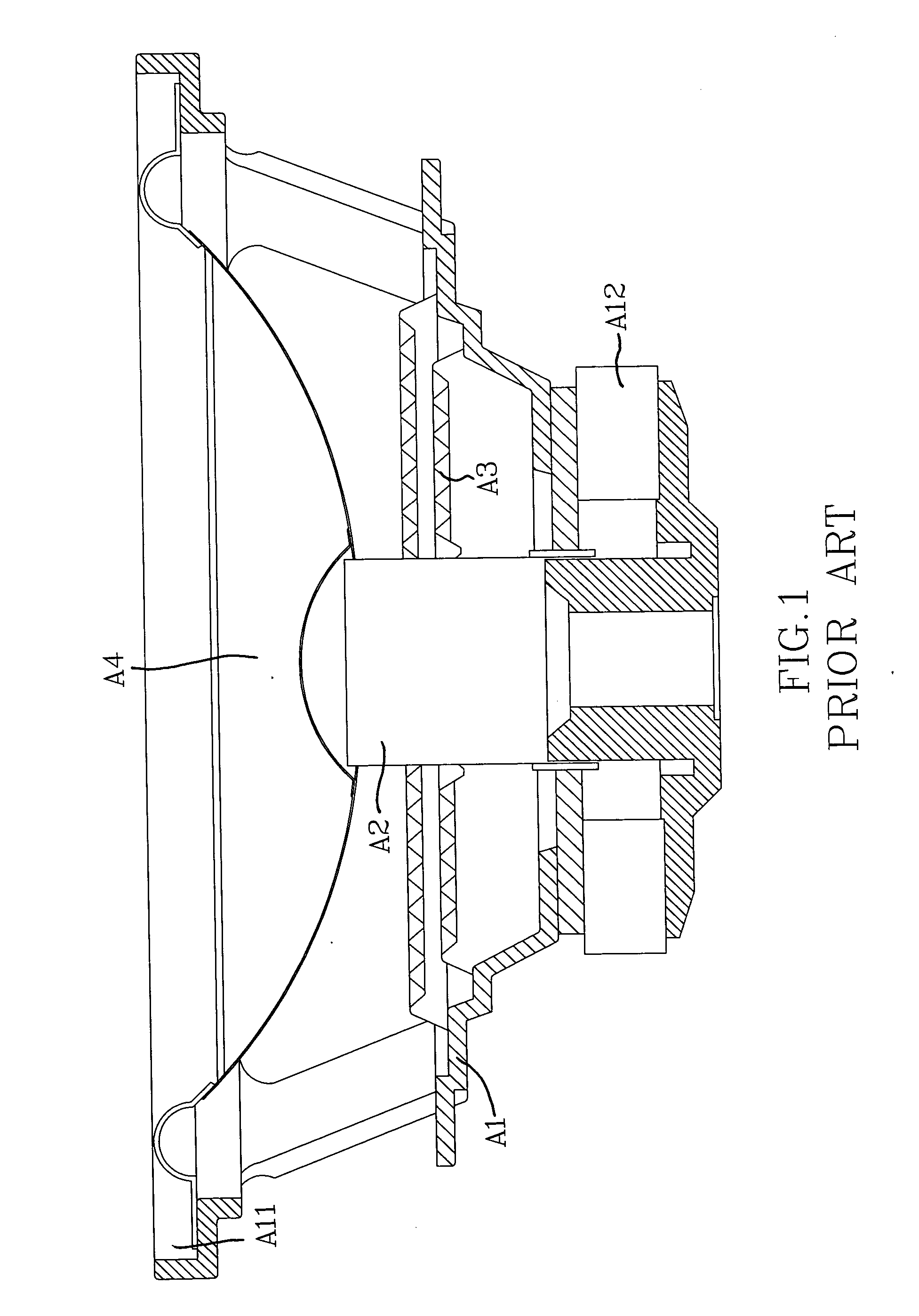
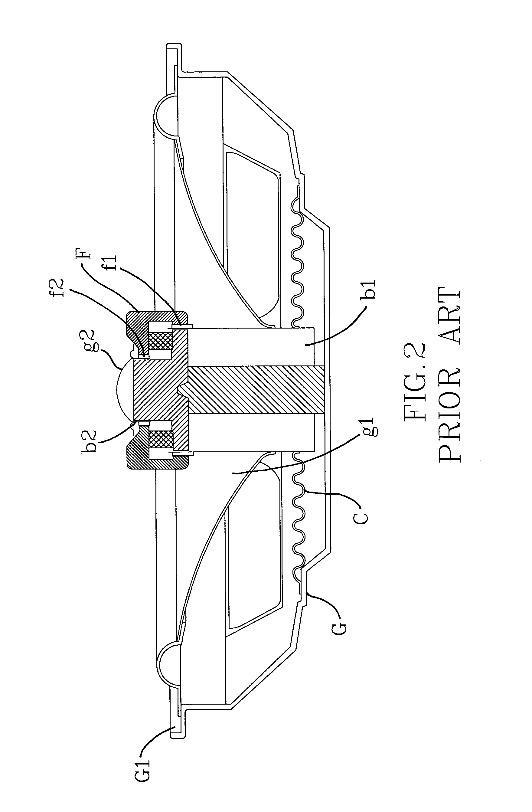
However, the assembly of the single circuit dual output speaker structure is more complicated, and seems to be quite fragile since only a cylindrical pillar is used for the support without the design of any accessory support.
The structure of the speaker will be deformed easily when it is collided, and such structure only allows users to hold the outer frame of the expanded opening of the support retainer, and thus making the assembling and maintenance of the speaker very inconvenient.

Method used


Image

  • Single magnetic circuit dual output speaker
  • Single magnetic circuit dual output speaker
  • Single magnetic circuit dual output speaker

Examples


Embodiment Construction

[0017] To make it easier for the examiner to understand the structure, and overall operation of this invention, the specification accompanied by the drawings is described as follows. Please refer to FIGS. 3 to 6. The improved single magnetic circuit dual output speaker in accordance with this invention comprises: [0018] a support retainer 1, further comprising an expanded opening 11 at its front end, a bridge 9 disposed above the expanded opening 11, a magnetic circuit 5 inwardly disposed in the middle of the bridge 9, and a vibrating space 51, 52 disposed on each of both sides of the magnetic circuit 5; [0019] a first voice coil 2, disposed in the vibrating space 51 on one side of the magnetic circuit 5; [0020] a second voice coil 6, disposed in the vibrating space 52 on the other side of the magnetic circuit 5; [0021] a first diaphragm 7, disposed above the expanded opening 11 of the support retainer and its internal diameter being stuck with the first voice coil 2; [0022] a secon...


PUM


Abstract

The present invention discloses an improved single magnetic circuit dual output speaker, comprising a support retainer with an expanded opening at its front end, a bridge disposed across the opening, a magnetic circuit wound and fixed inwardly in the middle of the bridge, a vibrating space disposed on each of both sides of the magnetic circuit, a first voice coil disposed in the vibrating space on one side of the magnetic circuit, a second voice coil disposed in the vibrating space on the other side of the magnetic circuit, a first diaphragm disposed on the expanded opening of the support retainer and having its internal diameter stuck with the first voice coil, a second diaphragm disposed on the expanded opening of the support retainer and having its internal diameter stuck with the second voice coil, and a damper disposed at the back of the support retainer and stuck with the first voice coil, such that the magnetic circuit is mounted at the front of the support retainer by the bridge to provide the dual outputs of high and low pitches by a single body structure, and the bridge can be used to facilitate its holding during assembling and maintenance.

Description

BACKGROUND OF THE INVENTION [0001] 1. Field of the Invention [0002] The present invention relates to an improved speaker, more particularly to an improved single magnetic circuit dual output speaker adopting a bridge structure as reinforcement for the design, not only providing a better protection on the magnetic circuit, but also facilitating the grip by holding the bridge during the assembling and maintenance of the speaker. [0003] 2. Description of the Related Art [0004] Wonderful music is a major entertainment that enriches our life and relaxes our mind and body. Due to the extensive demand of the market, speaker manufacturers keep on enhancing the output of speakers to stimulate the consumption of the market, and also try their very best to develop more powerful speakers with stylish appearance or sound quality, and therefore new models are introduced to the market from time to time. [0005] Please refer to FIG. 1 for the traditional speaker structure. The magnetic circuit A12 i...

Claims


Application Information

Patent Timeline
Patent Type & Authority Applications(United States)
IPC IPC(8): H04R1/24
CPCH04R1/24
Inventor PENG, JACK
Owner MEILOON INDAL
Learn More