Single use lancet assembly

a single-use, lancet technology, applied in the field of single-use lancet assembly, can solve the problems of inconvenient use, subsequent, and inconvenient use of disposable devices, and achieve the effect of preventing further movement and preventing subsequent use of contaminated lancets

Inactive Publication Date: 2005-03-31
STAT MEDICAL DEVICES
View PDF99 Cites 115 Cited by
  • Summary
  • Abstract
  • Description
  • Claims
  • Application Information

AI Technical Summary

Benefits of technology

[0013] In order to ensure that lancet device can only be used a single time, the present single use lancet device further includes abutment structure cooperatively disposed between the housing and the lancet. The abutment structure is configured to prevent the lancet from moving into the cocked orientation after movement into the piercing orientation. Preferably, the abutment structure includes a shoulder element and a restrictor panel operatively associated with the lancet and the housing. In particular, the shoulder element is structured to pass over the restrictor panel when the lancet moves from its cocked orientation to its piercing orientation. Conversely, however, when a user attempts to move the lancet back into the cocked orientation after it moved into the piercing orientation, the restrictor panel abuts the shoulder element preventing further movement. As a result, movement of the lancet into the cocked orientation is prevented once the lancet has been used a single time, and subsequent uses of a contaminated lancet are prevented.

Problems solved by technology

While existing single use devices are generally effective for achieving the piercing of the skin required for effective operation, such single use, disposable devices typically do not incorporate a large number of safety features to ensure the safe use and disposal of the device.
Unfortunately, most currently available single use lancet devices are configured such that after a use thereof has been achieved, it is possible for a patient to re-cock the device, thereby allowing for a subsequent, inappropriate use.

Method used


Image

  • Single use lancet assembly
  • Single use lancet assembly

Examples


Embodiment Construction

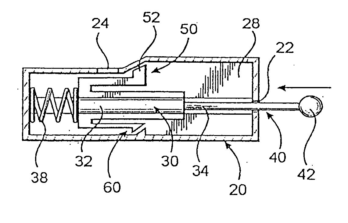
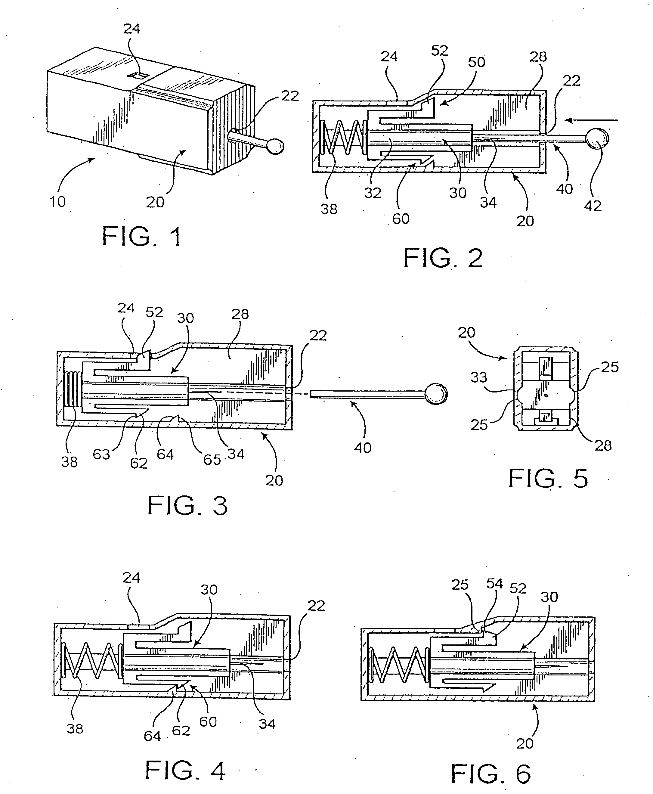
[0022] Shown throughout the Figures, the present invention is directed towards a single use lancet device, generally indicated as 10. In particular, the single use lancet device 10 of the present invention includes a housing, generally indicated as20. The housing 20 is preferably substantially small and compact, and may be made of one or a plurality of segments, preferably of a generally rigid, disposable material, such as plastic. The housing 20 includes an at least partially open interior 28 and at least one access opening 22 defined therein. The open interior 28 of the housing 20 is preferably sized and configured to effectively receive a lancet, generally 30 therein.

[0023] In particular, the lancet device 10 of the present invention also comprises a lancet 30. The lancet 30 preferably includes a body 32 and a piercing tip 34. The piercing tip 34 is what will be used to pierce a person's skin so as to draw blood to be utilized for a sample and or test procedure. Moreover, the bo...


PUM


Abstract

A single use lancet device having a housing, with an open interior and an access opening defined therein, a lancet, with a body and a piercing tip, and disposed in the open interior of the housing so as to move between a cocked orientation and a piercing orientation, a driving assembly structured to move the lancet into the piercing orientation, and a restrictor assembly having a shoulder element and a restrictor panel operatively associated with the lancet and the housing and structured to pass over the restrictor panel upon the lancet moving from its cocked orientation to its piercing orientation, and to abut the restrictor panel upon attempted movement of the lancet back into its cocked orientation after movement into the piercing orientation, thereby preventing the lancet from moving back into the cocked orientation and preventing re-use of a contaminated piercing tip.

Description

CLAIM OF PRIORITY [0001] The present application is a Continuation-In-Part application of previously filed, now pending application having Ser. No. 09 / 903,877 which was filed on Jul. 10, 2001, which is a continuation-in-part patent application having Ser. No. 09 / 432,351 which was filed on Nov. 2, 1999 and which issued as U.S. Pat. No. 6,258,112 on Jul. 10, 2001, both of which are hereby incorporated by reference.BACKGROUND OF THE INVENTION [0002] 1. Field of the Invention [0003] The present invention relates to a single use lancet assembly which is substantially compact, yet effective for piercing a patient's finger or other body part to obtain a blood sample. The single use lancet device is further configured to be substantially safe to transport and to ensure that subsequent uses of a contaminated lancet tip cannot occur. [0004] 2. Description of the Related Art [0005] Lancets are commonly utilized instruments which are employed both in hospitals and other medical facilities, as w...

Claims


Application Information

Patent Timeline
Patent Type & Authority Applications(United States)
IPC IPC(8): A61B5/15
CPCA61B5/15142A61B5/1411A61B5/150022A61B5/150183A61B5/150412A61B5/150564A61B5/150618A61B5/150717A61B5/150916A61B5/15113A61B5/15117A61B5/1513A61B5/15144
Inventor SCHRAGA, STEVEN
Owner STAT MEDICAL DEVICES
Why Eureka
Try Eureka