Glass fixing grommet

a technology of fixing grommets and screws, which is applied in the direction of mechanical equipment, transportation and packaging, wing accessories, etc., can solve the problems of difficult to repeatedly use glass fixing grommets, unstable glass attached to the elevating mechanism, and loosening of the fixing screw, etc., to achieve smooth screwing of the bolt in the nut member, easy receipt, and smooth screwing

Inactive Publication Date: 2005-04-07
NIFCO INC +1
View PDF17 Cites 23 Cited by
  • Summary
  • Abstract
  • Description
  • Claims
  • Application Information

AI Technical Summary

Benefits of technology

[0013] According to a third aspect of the invention, the first and second supporting plates are provided with engaging pieces for engaging with each other in a state that one of the cylinders is fitted in the other of the cylinders to regulate a space between the first and second supporting plates. Accordingly, when the engaging pieces engage with each other, even if the axial center of the female screw hole of the nut member is inclined with respect to the axial center of the bolt, it is possible to change the posture of the nut member to a desired one from the fitting viewpoint through a pushing force of the bolt when the bolt is screwed in the nut member. Therefore, when the bolt is pressed against the female screw hole of the nut member, it is possible to smoothly screw the bolt in the nut member until completion.
[0014] According to a fourth aspect of the invention, the second supporting plate is formed of an inner plate and an outer plate facing the inner plate to form a receiving space therebetween. The nut member is disposed in the receiving space, and a deformable supporting member is disposed between the nut member and the outer plate. Accordingly, it is possible to precisely hold the nut member in the receiving space with the deformable supporting member. Even if the window glass has a thickness smaller than usual and the second and first supporting plates hold the window glass peripheral edge portion in a state that the second supporting plate is inclined toward the first supporting plate, the deformable supporting member is deformed by the pressing force of the bolt with respect to the nut member, so that the nut member is maintained in a desired posture and the bolt is precisely screwed in the nut member.
[0015] According to a fifth aspect of the invention, the nut member is formed of an annular plate portion and a cylindrical portion connected to a central hole peripheral edge portion of the annular plate portion and having a female screw on an inner peripheral surface thereof. The annular plate portion is disposed in the

Problems solved by technology

Accordingly, the tapping screw may be loosened and the glass attached to the elevating mech

Method used


Image

  • Glass fixing grommet
  • Glass fixing grommet
  • Glass fixing grommet

Examples


Embodiment Construction

[0040] Hereunder, embodiments of the present invention will be described with reference to the accompanying drawings.

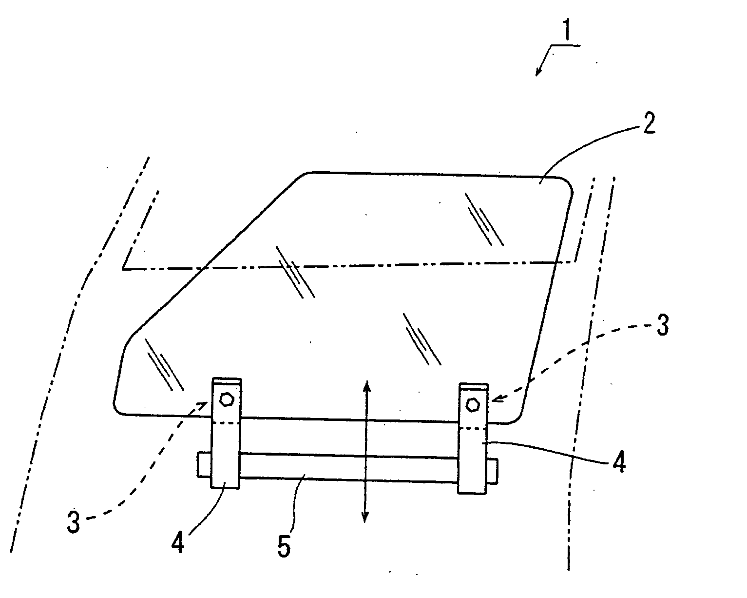
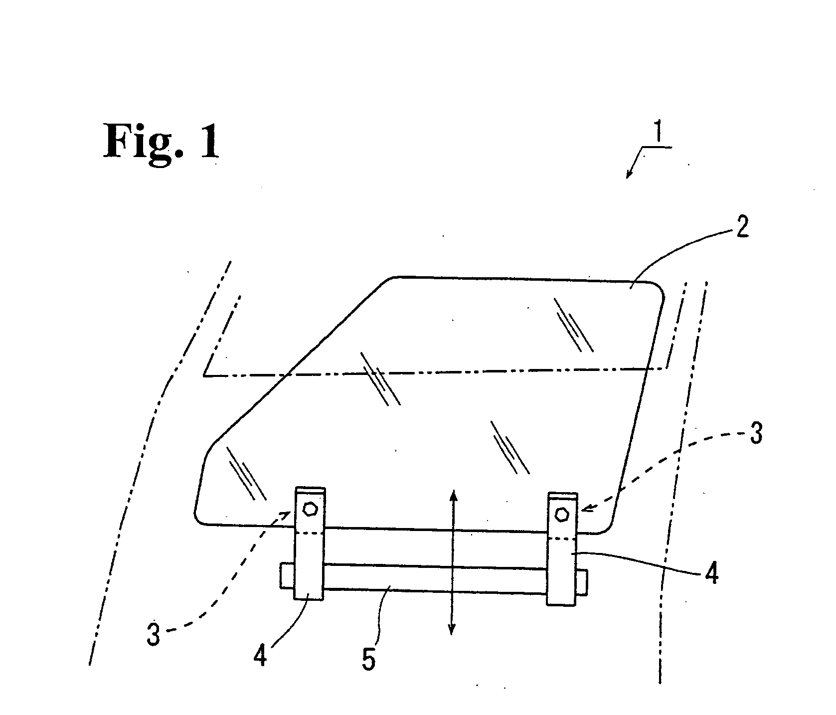
[0041] In FIG. 1, reference numeral 1 denotes a side door of an automobile, and the side door 1 is provided with a widow glass 2. Carrying plates or mounts 4 are attached to lower portions of the window glass 2 at two positions, i.e. front and rear positions thereof, through glass fixing grommets 3 according to an embodiment of the present invention. The carrying plates 4 are connected to an elevating table 5 constituting a portion of an elevating mechanism (hereinafter, reference numeral 5 is used to indicate the elevating mechanism). The window glass 2 moves in the vertical direction with the elevating mechanism 5.

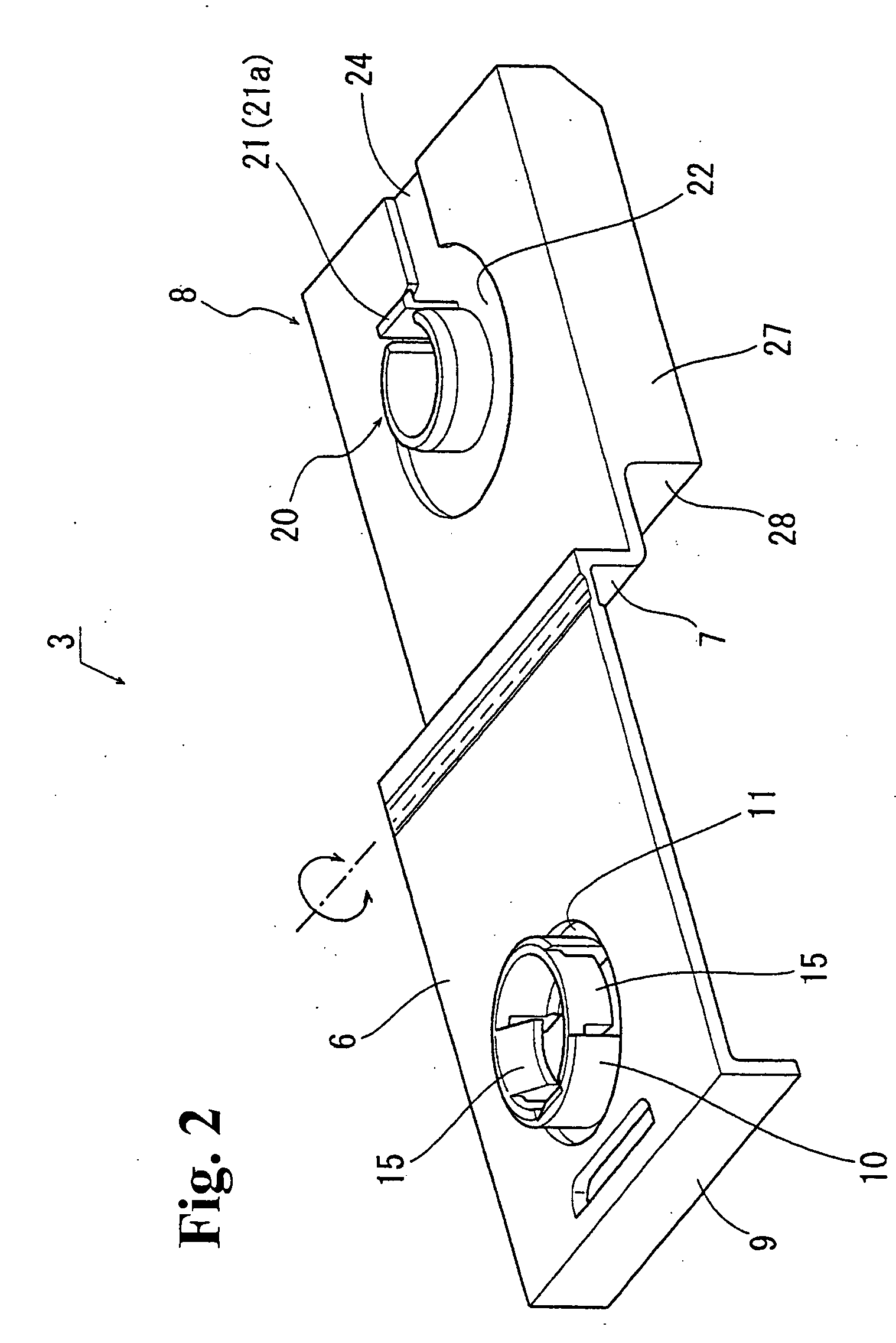
[0042] In the present embodiment, as shown in FIG. 2, the glass fixing grommet 3 includes a first supporting plate portion 6 as a first supporting plate, a connecting plate portion 7 as a connecting plate, and a second supporting plate portion 8 as a sec...


PUM


Abstract

A glass fixing grommet fixes a glass with a hole to a mount and includes first and second supporting plates. The first supporting plate is attached on one surface of the glass and has a first cylinder portion with a bolt inserting hole for inserting a bolt therein. The second supporting plate is attached on the other surface of the glass to face the first supporting plate. The second supporting plate includes a second cylinder portion to be fitted with the first cylinder portion with a bolt exit, and a nut holding member situated adjacent to the bolt exit for holding a nut thereat. When the first and second supporting plates sandwich the glass, the bolt passes through the mount and the first and second supporting plates to engages the nut to fix the glass to the mount.

Description

BACKGROUND OF THE INVENTION AND RELATED ART STATEMENT [0001] The present invention relates to a glass fixing grommet to be used when a window glass is attached to a mount. [0002] When a window glass is attached to a mount such as a window glass elevating mechanism, a glass fixing grommet has generally been used as disclosed in Japanese Patent No. 3285987. The glass fixing grommet includes a first supporting plate to be attached on one surface of a window glass peripheral edge portion having a hole and a second supporting plate to be attached on the other surface of the window glass peripheral edge portion to face the first supporting plate. The first supporting plate includes one of inner and outer cylinders to be fitted into each other. The second supporting plate includes the other of the inner and outer cylinders. [0003] When the first supporting plate and the second supporting plate face each other and hold the glass peripheral edge portion, both cylinders fit into each other in...

Claims


Application Information

Patent Timeline
IPC IPC(8): B60J1/17E05F11/38F16B5/00F16B5/02
CPCE05F11/385E05F2011/387E05Y2800/684E05Y2600/53E05Y2900/55E06B3/5436
Inventor YOSHII, HIROYUKIYOKOYAMA, SHIGEHARUKAJIYAMA, TOMOHIRO
Owner NIFCO INC
Why Eureka
Try Eureka