Valve timing control system for internal combustion engine

a timing control system and internal combustion engine technology, applied in the direction of machines/engines, non-mechanical valves, output power, etc., can solve the problems of difficult to hold the engine valve in desired timing, response delay, and engine valve cannot be held in desired timing

Inactive Publication Date: 2004-03-16
HONDA MOTOR CO LTD
View PDF9 Cites 13 Cited by
  • Summary
  • Abstract
  • Description
  • Claims
  • Application Information

AI Technical Summary

Benefits of technology

According to this valve timing control system, the response delay of the actuator is predicted by a response delay prediction value, and output timing in which the drive signal for driving the actuator is output is set according to the predicted response delay prediction value. Further, holding timing in which the valve is held by the actuator is controlled by outputting the drive signal to the actuator, based on the set output timing. Therefore, the operation of the actuator can be started in proper timing dependent on the predicted response delay of the actuator, which makes it possible to properly hold the valve in predetermined appropriate holding timing while compensating for the response delay of the actuator and enabling efficient operation of the actuator.
According to this preferred embodiment, the output start offset time period is calculated as the response delay prediction value, and the output start timer counts up to a time going back from a reference time corresponding to a predetermined reference crank angle position by the output start offset time period, thereby causing the drive signal to start to be output to the actuator at the time. This makes it possible to cause the drive signal to start to be delivered in appropriate timing with accuracy, in synchronism with the rotation of the cam, and cause the operation for holding the valve to be properly completed by the time the reference crank angle position is reached.

Problems solved by technology

In the conventional valve timing control system, however, there occurs a response delay between a time an instruction is delivered for holding the engine valve and a time a holding operation is actually carried out on the engine valve.
The response delay makes it difficult to hold the engine valve in desired timing.
Particularly, in this valve timing control system, the solenoid actuator is driven when the engine valve reaches the open position by the operation of the cam, and therefore, when the operating condition changes, there is a fear that the engine valve cannot be held in desired timing due to the delayed response of the solenoid actuator, making it impossible to achieve a desired valve lift curve or even hold the engine valve.
In such a case, the combustion state is degraded to adversely affect exhaust emissions.
Further, the rise of the magnetic flux becomes slower as the power supply voltage is lower, and becomes relatively slower with respect to the operating speed of the engine valve as the engine rotational speed is higher.
This increases the possibility of failure in holding the engine valve.
Further, if a hydraulic actuator is employed for the mechanism for holding the engine valve, instead of the solenoid actuator, the rise in the hydraulic pressure becomes slower as the oil temperature is lower.
Further, as the engine rotational speed is higher, the response of the holding mechanism becomes slower, which can also increase the possibility of failure in holding the engine valve.
When a valve is actuated by a cam in the valve-opening direction, the valve displacement speed can be made slower by a disturbance, such as frictional resistance and biting of wear particles, causing a decrease in the lift of the valve, which makes it impossible to obtain predetermined lifting timing.
Therefore, in case a decrease in the valve lift occurs owing to such a disturbance described above, the armature can be positioned too far from the electromagnet when the valve is to be held, which makes it impossible for the electromagnet, which is energized at this time, to attract the armature thereto, resulting in an error in holding of the valve (loss of synchronization).
In contrast, if constant-current control is carried out before the valve is held, the current is limited so as to allow only a predetermined or lower amount of current to flow, so that if the armature is not within a predetermined distance of the electromagnet due to a decreased valve lift caused by the disturbance, there is a fear that the failure of holding of the valve can occur.

Method used


Image

  • Valve timing control system for internal combustion engine
  • Valve timing control system for internal combustion engine
  • Valve timing control system for internal combustion engine

Examples


Embodiment Construction

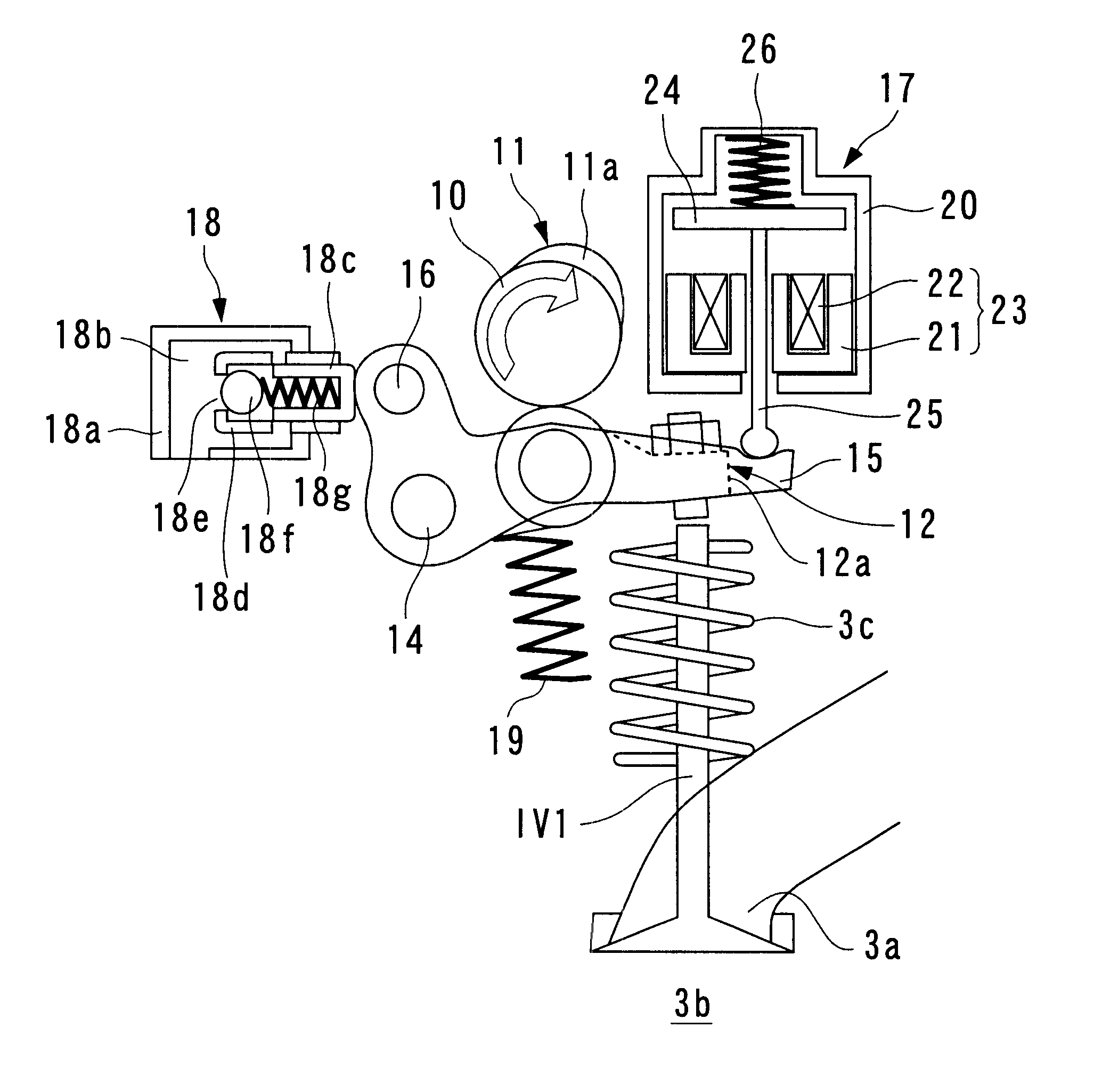
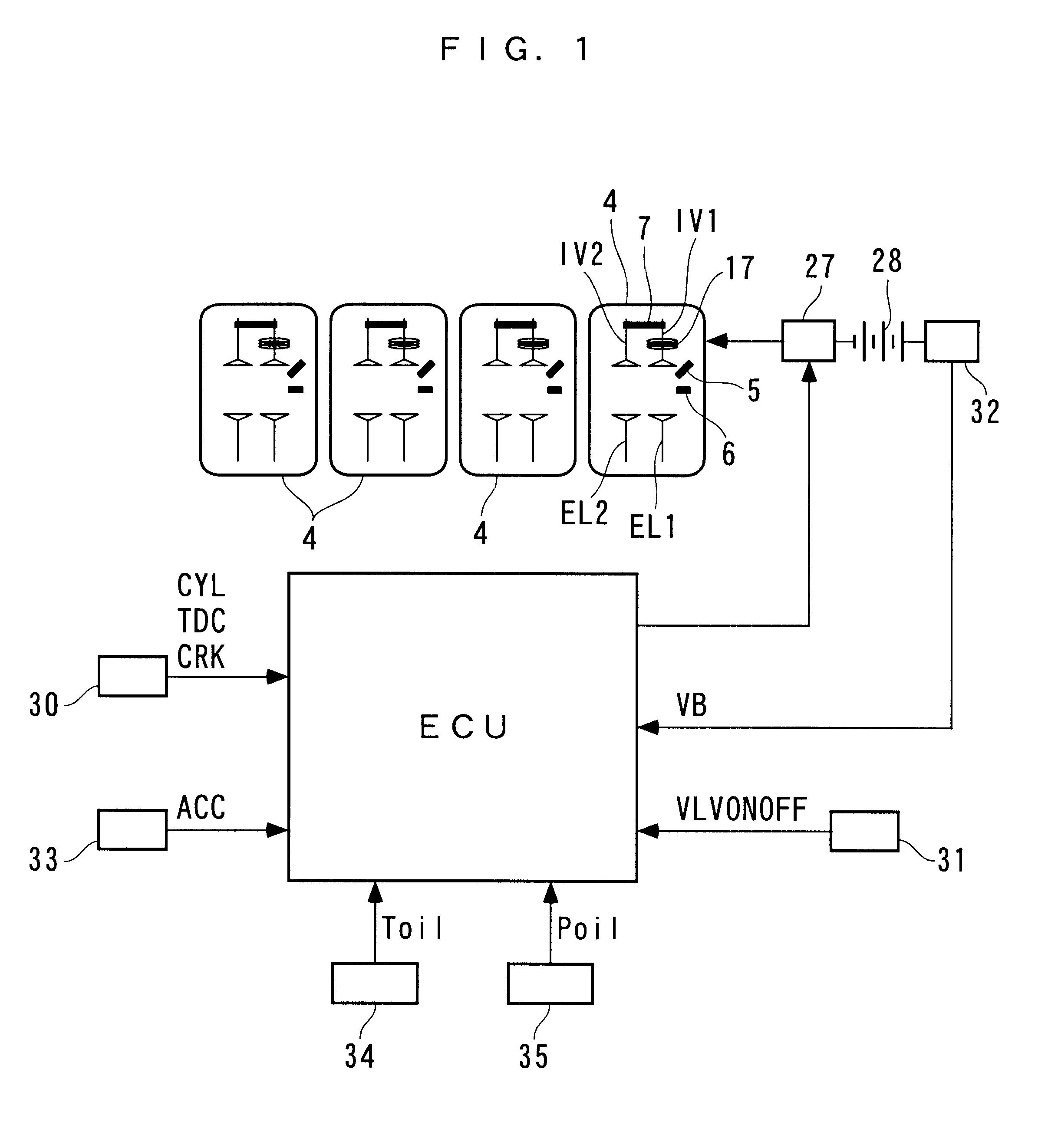
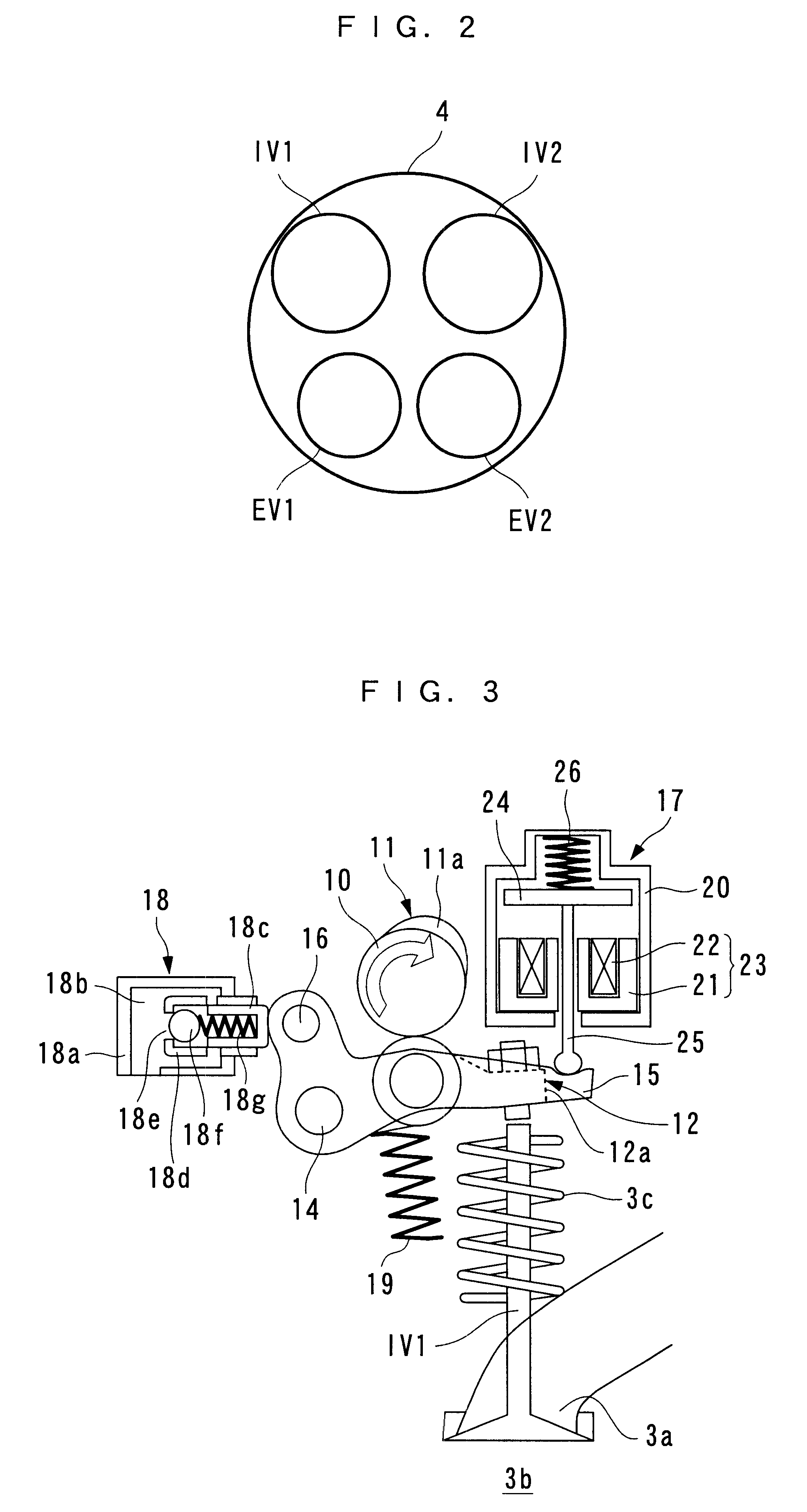
Hereafter, a valve timing control system for an internal combustion engine, according an embodiment of the invention, will be described with reference to the drawings. FIG. 1 schematically shows the arrangement of an internal combustion engine incorporating a valve timing control system to which the present invention is applied. The illustrated internal combustion engine (hereinafter referred to as "the engine") 3 is a four-cylinder in-line DOHC gasoline engine installed on a vehicle, not shown. Each cylinder 4 is provided with first and second intake valves IV1, IV2, and first and second exhaust valves EV1, EV2 (see FIG. 2), and further with an injector 5 for injecting fuel into an intake port 3a and a spark plug 6 for igniting the air-fuel mixture.

As illustrated in FIG. 3 showing an example of the first intake valve IV1, each of the intake valves IV1, IV2 is arranged such that it is movable between a closed position (shown in FIG. 3) in which the intake port 3a is closed and an op...


PUM


Abstract

A valve timing control system for an internal combustion engine is provided which is capable of ensuring reliable holding of a valve by an actuator, and attaining energy saving by efficient operation of the actuator. The valve timing control system controls valve-closing timing of a valve opened by a cam provided on a camshaft, by temporarily holding the valve. A response delay of the actuator is predicted as a response delay prediction value. Output timing is set in which a drive signal for driving the actuator is output, according to the predicted response delay prediction value. Holding timing is controlled in which the valve is held by the actuator, by outputting the drive signal to the actuator, based on the set output timing.

Description

1. Field of the InventionThis invention relates to a valve timing control system for an internal combustion engine, which controls timing for closing a valve opened by a cam provided on a camshaft of the engine by temporarily holding the valve by an actuator.2. Description of the Prior ArtConventionally, a valve timing control system of this kind has been proposed e.g. in Japanese Laid-Open Patent Publication (Kokai) No. 63-289208. This valve timing control system opens and closes engine valves by cams provided on a camshaft via rocker arms, and includes holding mechanisms for holding the engine valves in respective open positions. The holding mechanisms are each implemented by a solenoid actuator comprised of a solenoid fixed to the cylinder head and an armature fixed to a valve stem of an engine valve. The energization of the coil of the solenoid is controlled by a control unit. The armature is arranged in a manner opposed to the solenoid such that when the engine valve is actuate...

Claims


Application Information

Patent Timeline
Patent Type & Authority Patents(United States)
IPC IPC(8): F01L9/04F01L1/26F01L1/00F01L1/46F01L13/00F01L9/20F02D13/02
CPCF01L1/26F01L1/267F01L1/46F01L9/04F01L2013/0089F01L9/20
Inventor YAMAKI, TOSHIHIROOZAWA, HIDETAKASAKAI, HISAOABE, KENJI
Owner HONDA MOTOR CO LTD
Why Eureka
Try Eureka