Directly electrified ceiling grid

a ceiling grid and direct electrification technology, applied in the direction of ceilings, walls, building components, etc., can solve the problems of increasing the consumption of low voltage electrical power, inefficient transforming the relatively high voltage ac utility, and consuming appreciable electric power in a standby mod

Inactive Publication Date: 2010-06-10
USG INTERIORS INC
View PDF15 Cites 13 Cited by
  • Summary
  • Abstract
  • Description
  • Claims
  • Application Information

AI Technical Summary

Benefits of technology

[0007]The inventive scheme is particularly adapted to linear ceiling designs where light strips and other accessories are arranged along a continuous straight line spanning the ceiling. This linear arrangement can be implemented with minimal modification or customization of standard grid elements, and with limited specialized componentry. In the disclosed embodiment, channels for lighting and other accessories are created between sections of standard grid construction. The channels are established with custom brackets in the shape of an inverted U. The brackets serve to precisely hold the adjacent grid sections in parallel, spaced relation and provide clearance for light fixtures and other accessories such as air distributing equipment as well as hanger wire support points for the grid. The bracket or yoke is arranged to be fixed to main tees at the border of respective grid sections of opposite polarity. The bracket electrically isolates the main tees it serves to space by incorporating suitable insulators or being constructed entirely of electrically insulating material.

Problems solved by technology

As the use of electronics grows, the consumption of low voltage electrical power likewise grows.
Individual power supplies located at the site of or integrated in an electronic device, the most frequent arrangements today, are often quite inefficient in transforming the relatively high voltage AC utility power to a lower DC voltage required by an electronic device.
Typically, they can consume appreciable electric power in a standby mode when the associated electronic device is shut off.

Method used


Image

  • Directly electrified ceiling grid
  • Directly electrified ceiling grid
  • Directly electrified ceiling grid

Examples


Embodiment Construction

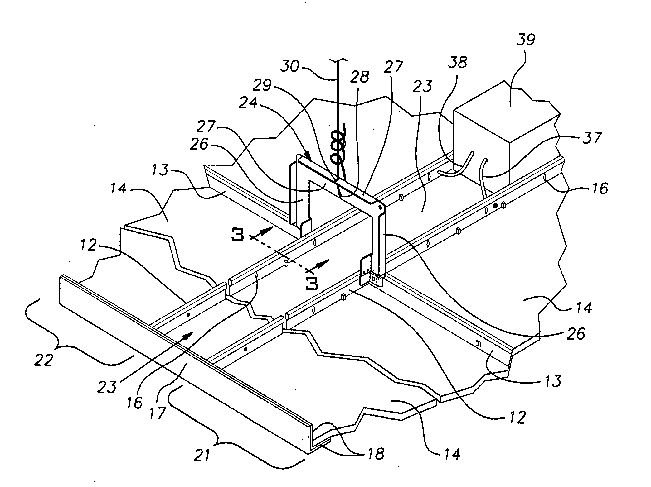
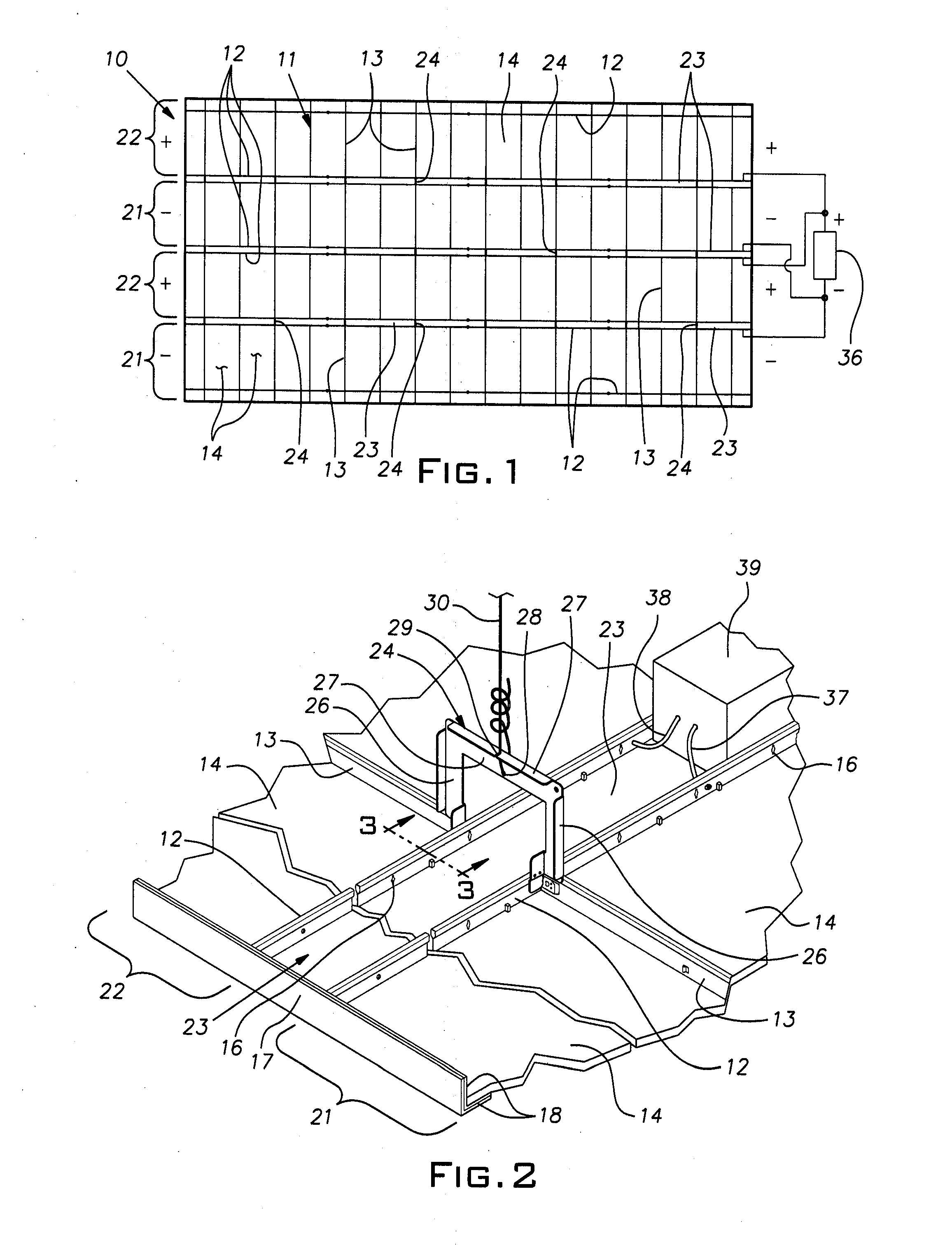
[0012]FIG. 1 illustrates an example of a suspended ceiling 10 constructed with generally conventional components. The ceiling 10 comprises a rectangular grid system 11 of main runners or tees 12 and cross runners or tees 13 on which are carried ceiling tiles or panels 14. The grid runners or tees are in the form of inverted tees most commonly made of roll-formed sheet steel, galvanized and / or painted for corrosion resistance. The main tees 12 can be 10 or 12 feet long (or metric equivalent), and joined end-to-end to extend the length of the desired ceiling area. U.S. Pat. No. 6,729,100 discloses an example of an end connector suitable for joining the ends of conventional main tees 12. Cross tees 13 are typically 4′ or 2′ long (or metric equivalent) and are joined end-to-end by connectors such as shown in U.S. Pat. No. 5,761,868. The ceiling panels 14 can be of any known construction either non-metallic and, therefore, non-conducting, or made of metal sheet stock and, therefore condu...


PUM


Abstract

An electrified grid for a suspended ceiling comprising first and second grid sections lying in a common ceiling plane, each grid section having metal main tees and metal cross tees intersecting with the main tees, the first and second sections being adjacent one another and having respective main tees in parallel alignment and with a fixed spacing not substantially greater than the length of the cross tees, the grid sections being electrically insulated from one another whereby at least said main tees of fixed spacing can be held at opposite voltage polarities and an electrical or electrical device carried on or above the ceiling can be powered by electrical connection of separate ones of its leads to the metal tees of a respective one of said first and second grid sections.

Description

BACKGROUND OF THE INVENTION[0001]The invention relates to suspended ceiling structures and, in particular, to electrification of such ceiling structures.PRIOR ART[0002]Commercial building spaces such as offices, laboratories, light manufacturing facilities, health facilities, meeting and banquet hall facilities, educational facilities, common areas in hotels, apartments, retirement homes, retail stores, restaurants and the like are commonly constructed with suspended ceilings. These suspended ceiling installations are ubiquitous, owing to their many recognized benefits. Such ceilings ordinarily comprise a rectangular open grid suspended by wire from a superstructure and tile or panels carried by the grid and enclosing the open spaces between the grid elements. The most common form of grid elements has an inverted T-shaped cross-section. The T-shape often includes a hollow bulb at the top of the inverted stem of the T-shape. A popular variant of this standard T-shape includes a downw...

Claims


Application Information

Patent Timeline
Patent Type & Authority Applications(United States)
IPC IPC(8): E04C2/52E04B9/18E04B9/22
CPCE04B9/006E04B9/18E04B9/06
Inventor LEHANE, JAMES J.GULBRANDSEN, PEDER
Owner USG INTERIORS INC
Why Eureka
Try Eureka