Position adjustment mechanism and recording apparatus

a technology of position adjustment mechanism and recording apparatus, which is applied in the direction of belt/chain/gearing, printing, belt/chain/gearing, etc., can solve the problem of deviating inclination angle of the head unit, and achieve the effect of accurate adjustment of the position of the recording portion

Inactive Publication Date: 2012-02-23
SEIKO EPSON CORP
View PDF8 Cites 16 Cited by
  • Summary
  • Abstract
  • Description
  • Claims
  • Application Information

AI Technical Summary

Benefits of technology

[0007]An advantage of some aspects of the invention is to provide a position adjustment mechanism and a recording apparatus capable of accurately holding a first member and a second member in a state where a position of the second member with respect to the first member is adjusted.
[0009]According to the aspect of the invention, in the state where the position of the second member with respect to the first member is adjusted by the cam, when the second member is fixed by the screw to the fixing portion which is provided in the forming area of the cam surface of the cam in the first member, the abutment position of the cam surface of the cam and the fixing position fixed by the screw come very close to each other in the second member. Therefore, it is possible to accurately hold the first member and the second member in a state where the position of the second member with respect to the first member is adjusted.
[0011]According to the position adjustment mechanism of the aspect of the invention, it is possible to accurately adjust the position of the second member with respect to the first member by each cam.
[0017]In general, since the carriage is supported so as to be movable in a guide shaft in which the end of the upstream side in the transport direction of the recording medium in the carriage is extended in the scanning direction, a space capable of installing components in a side surface of the guide shaft side in the carriage is not substantially provided. With regard to this, according to the recording apparatus of the aspect of the invention, since each member for rotating the cam shaft can be installed in the both side surfaces in the scanning direction in the carriage and the side surface of a side which is opposite to the guide shaft side in the carriage, each cam can be easily rotated by operating each member.
[0019]According to the recording apparatus of the aspect of the invention, it is possible to accurately adjust the position of the recording portion so that the nozzle forming area is parallel to a recording surface of the recording medium by each cam.

Problems solved by technology

Thereby, the fixing position of the sliding member is deviated due to the fastening through the fixing screws, and there is a problem in that the inclination angle of the head unit may be deviated.

Method used


Image

  • Position adjustment mechanism and recording apparatus
  • Position adjustment mechanism and recording apparatus
  • Position adjustment mechanism and recording apparatus

Examples


modified embodiment

[0070]In addition, the above-described embodiment may be modified to other embodiments as described below.

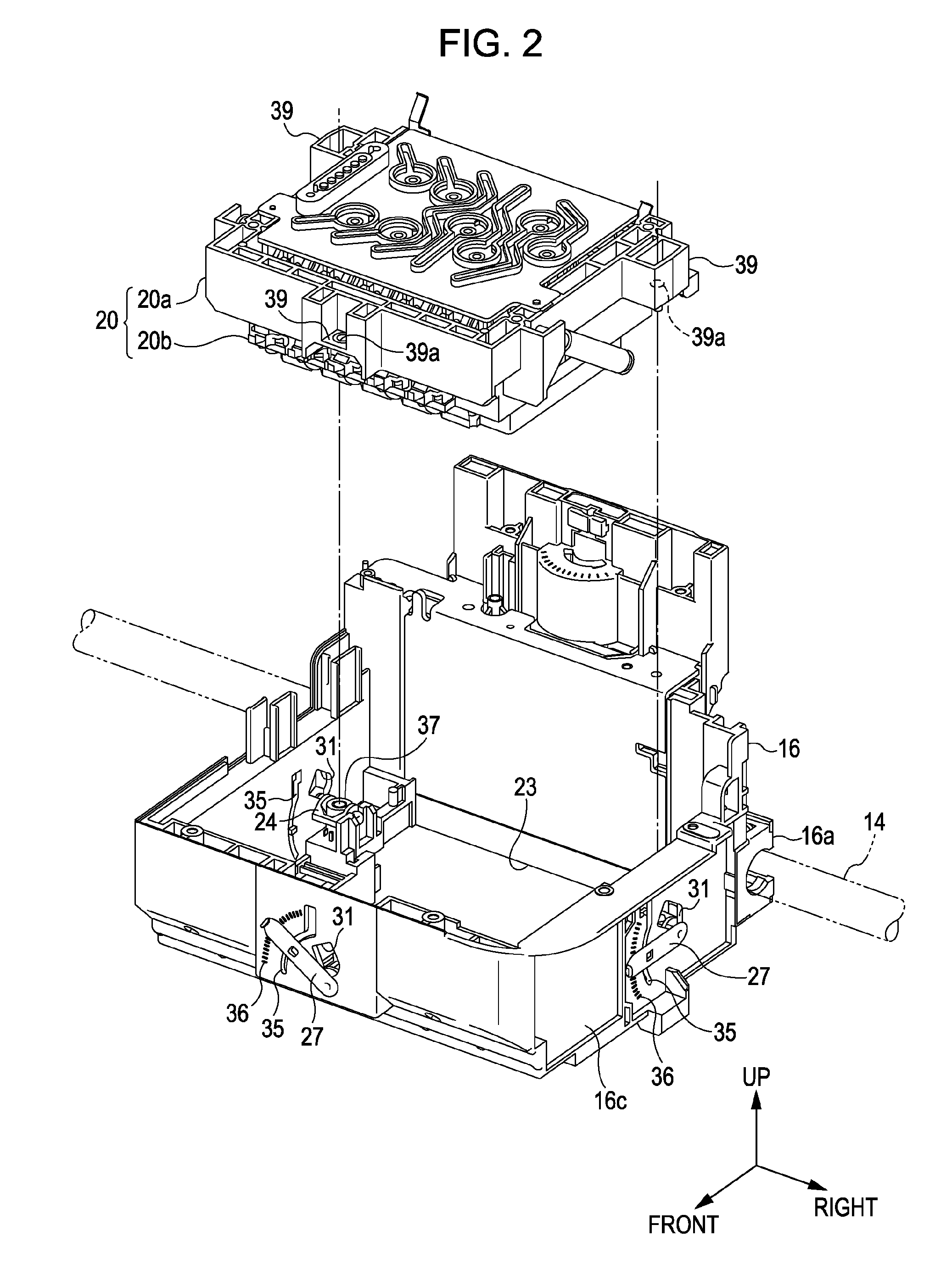
[0071]At least one of the rotary cams 24 may be modified to a slide type cam.

[0072]Any one of two side walls other than the side walls of both sides in the axis direction of each cam 24 may be omitted.

[0073]Each cam 24 is not necessarily disposed on the outside of the nozzle forming area R in the direction (the up-down direction) which is perpendicular to the nozzle forming area R.

[0074]The axis direction of each cam 24 may be the same as each other.

[0075]In the peripheral wall 16c of the carriage 16 in which each bearing portion 32 is installed and each bearing plate 33 in which the bearing portion 34 is installed, the surface of each cam 24 side of the peripheral wall 16c and each bearing plate 33 does not necessarily come close to the surface (the outer peripheral surface) in which each shaft 26 is installed in each cam 24.

[0076]Each boss portion 37 is not necessarily dispose...


PUM


Abstract

A position adjustment mechanism is provided to adjust a position of second member with respect to a first member. The position adjustment mechanism includes: a cam that is provided in the first member so that a cam surface of the cam abuts the second member; and a fixing portion that is provided in a forming area of the cam surface in the first member and fixes the second member to the first member by screw in a state where the position of the second member with respect to the first member is adjusted by the cam.

Description

[0001]The entire disclosure of Japanese Patent Application No: 2010-183103, filed Aug. 18, 2010 is expressly incorporated by reference herein in its entirety.BACKGROUND[0002]1. Technical Field[0003]The present invention relates to a position adjustment mechanism and a recording apparatus.[0004]2. Related Art[0005]In general, as a recording apparatus in which a liquid is adhered to a recording medium and a recording processing is performed, an ink jet type printer is widely known in which ink (liquid) is ejected from each nozzle of a recording head mounted on a carriage to the recording medium and the printing is performed (for example, JP-A-2010-125832). In the above-described printer, in order to secure the printing accuracy, the position of the recording head with respect to the carriage is adjusted. That is, in the printer of JP-A-2010-125832, a sliding member which slides on a head unit (a recording portion) and defines the inclination angle of the head unit, and an adjustment e...

Claims


Application Information

Patent Timeline
Patent Type & Authority Applications(United States)
IPC IPC(8): B41J2/01F16H25/08
CPCB41J2/1752Y10T74/18296B41J29/02
Inventor YAJIMA, YASUSHIHIRUMA, DAISUKEHAMANO, RYOHARADA, NORIHITO
Owner SEIKO EPSON CORP
Why Eureka
Try Eureka