
C-frame slidable touch input apparatus for displays of computing devices

a touch input apparatus and computing device technology, applied in the direction of instruments, details of portable computers, lock applications, etc., can solve the problems of increased time and money for users, many users are not satisfied with the quality of touch screen products and/or the time required for installation, etc., to achieve the effect of convenient and quick

Inactive Publication Date: 2005-04-07
DURSO NICK P
View PDF8 Cites 115 Cited by
  • Summary
  • Abstract
  • Description
  • Claims
  • Application Information

AI Technical Summary

Benefits of technology

[0008] The purpose of the present invention is to provide an easy and quick way to convert any display, including liquid crystal display (LCD) or flat-screen display, to a touch screen display without taking apart or disassembling the display. The present invention is placed, oriented, positioned, or slipped over the display to allow the non-touch screen display to become a touch screen display; there is also a connection from the internal circuitry or processing component(s) or controller of the touch screen to the computing device.
[0009] Another purpose of the present invention is to provide a slipcover that protects the display screen from physical injury or damage. Since the cost of displays or monitors or view screens for computing devices can be quite considerable, the slipcover can provide an economical way to protect the valuable display from injury or wear and tear.
[0010] Another purpose of the present invention is to allow for easy communication with a computing device with a touch screen interface. With the growing and popular use of mobile and laptop computers for presentations, this invention provides an easier input access through a touch screen than with using a stylus, mouse, or other external input device. This facilitation of the input process allows for maximizing the usefulness and portability of mobile computing.
[0011] Another purpose of the present invention is to provide an economical and affordable way to provide access to a touch screen to a single or multiple users. Since the invention can be removed and replaced on any display easily, this invention allows operators to best maximize their resources and to apply use of a touch screen when needed.
[0012] Another purpose of the present invention is to provide an easy and cost-effective way to convert a non-touch screen display to a touch screen display without having to physically take apart or disassemble the display and / or computing device to install a touch screen. For example, instead of having to convert many non-touch screen displays and integrated computer / display machines with an internally installed touch screen, the user simply needs to slip over the instant invention over the needed displays to make the necessary conversion into a touch screen displays.
[0013] Another purpose of the present invention allows for making computers more accessible to users with handicaps or disabilities that prevent them from accessing computers via traditional input devices such as the keyboard and the mouse. These particular touch screen users can take advantage of using a finger, stylus, or other easy to use input to engage the touch screen. Additionally, since the present invention facilitates the transformation of a regular non-touch screen display into a touch screen display, users with handicaps and / or disabilities are further able to enjoy the benefits of using touch screen input devices to access a computing device and the Internet.

Problems solved by technology

This touch screen installation required additional time and money for a user.
In addition, due to the complexity of installation process of a touch screen to a display and the wide range of quality of different touch screens available in the marketplace, many users were not satisfied with the quality of the touch screen products and / or time required for installation.

Method used


Image

  • C-frame slidable touch input apparatus for displays of computing devices
  • C-frame slidable touch input apparatus for displays of computing devices
  • C-frame slidable touch input apparatus for displays of computing devices

Examples


Embodiment Construction

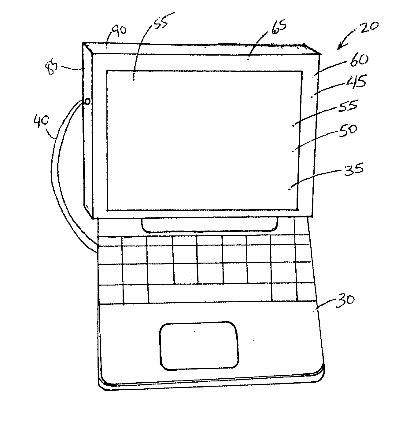
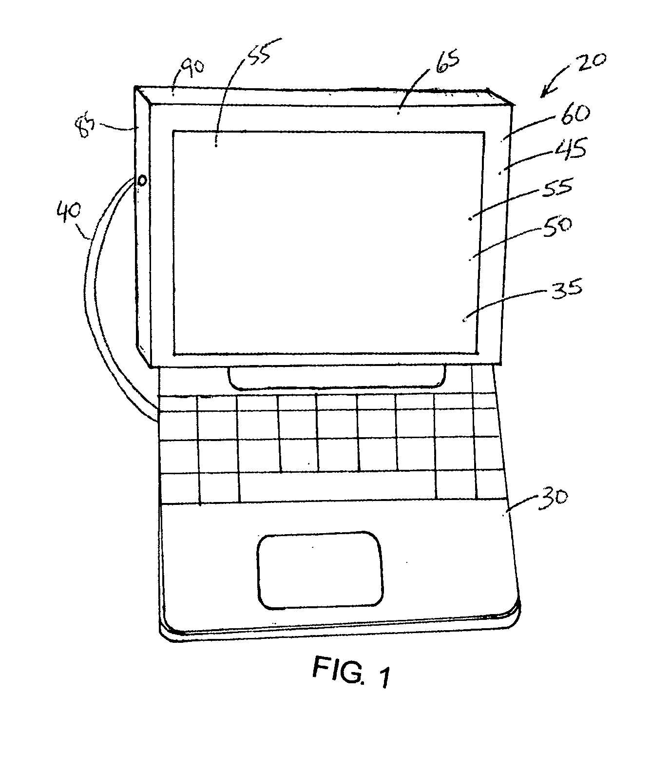
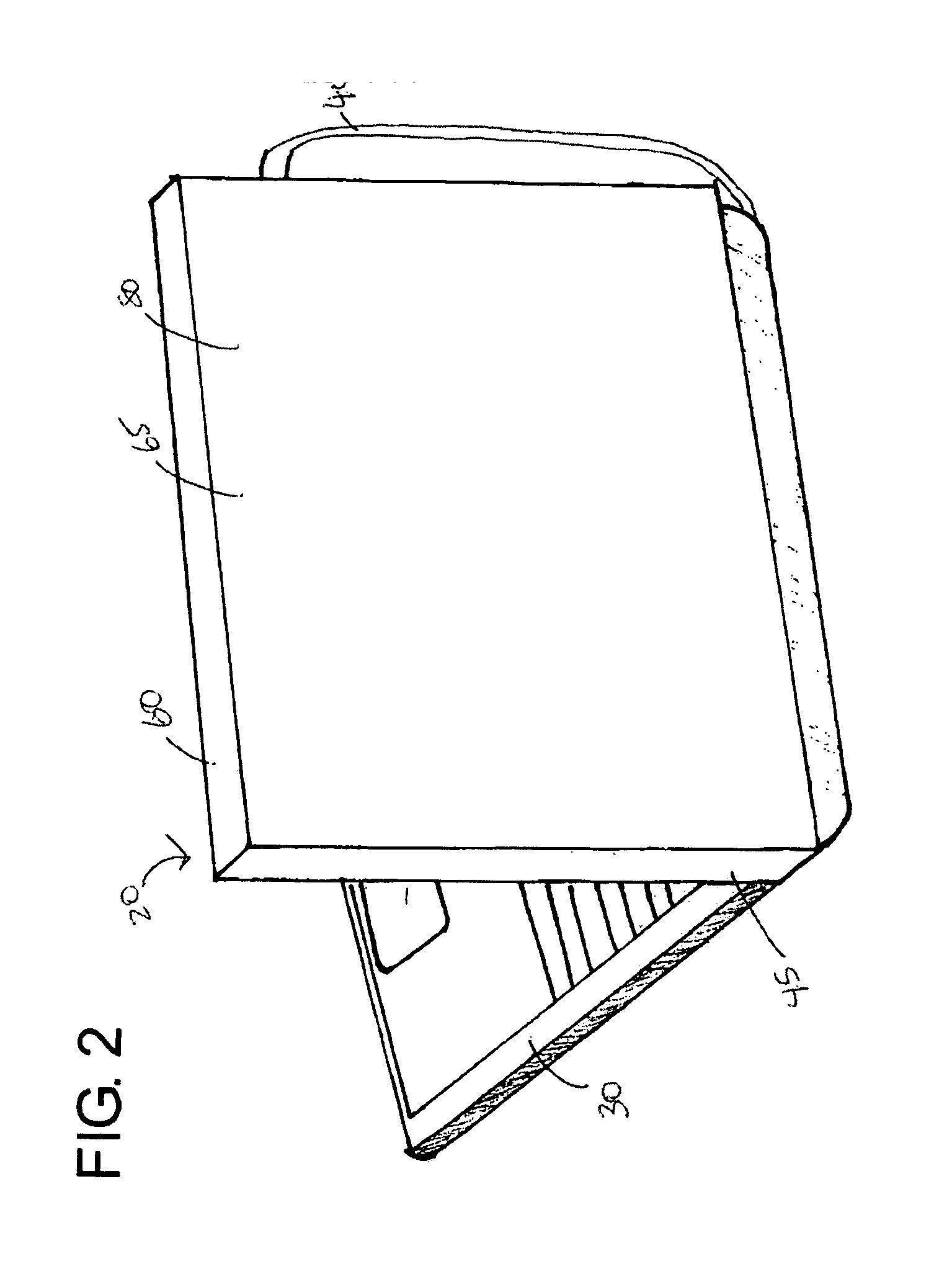
[0056] Referring to FIG. 1-8, there is illustrated a structure or a touch screen slipcover assembly 20 for adjustably converting a non-touch screen display 25, including but not limited to a liquid crystal display (LCD) and a flat-panel display, to a touch screen display.

[0057] The touch screen slipcover 20 for a computing device has a touch screen 35 on one surface; this slipcover slips over and acts like a sheath or surrounding cover or glove over and around the display 25 for a computing device 30. A connection 40, such as a Universal Serial Bus (USB) cord, connects a controller (not shown) of the touch screen (input device) to the computing device 30. The controller may be located on the back surface of the slipcover or integrated and compartmentalized within the slipcover casing 45. This invention will convert any non-touch screen display to a touch screen display to receive input from a user based on touch or pressure or other touch screen technologies.

[0058] As shown in FIG...


PUM


Abstract

This invention provides a slipcover touch input apparatus and structure for displays for computing devices that converts a non-touch screen display to a touch screen display. The slipcover assembly acts as a sheath or cover for the display, and the touch screen is mounted in a window or opening of the casing of the display so that the touch screen is oriented to mimic the position of the display. This touch screen slipcover can convert any display of a computing device into a touch screen display.

Description

BACKGROUND OF THE INVENTION [0001] 1. Priority Information: [0002] This application is a continuation in part of U.S. patent application Ser. No. 10 / 679,930, filed Oct. 5, 2003. [0003] 2. Field of the Invention: [0004] This invention relates to a structure suitable for converting a non-touch screen display into a touch screen display comprising a slipcover for a display for computing devices and other electronic devices that not only protects the display but also allows for conversion of a regular or non-touch screen display to a touch screen display. By allowing for easy conversion of a regular or non-touch screen display to a touch screen display, the user will realize significant cost and time savings, adaptability, and convenience. [0005] 3. Description of Related Art: [0006] Prior to the present invention, in order to convert a non-touch screen display to a touch screen display, the user needed to take apart and disassemble the display to install a touch screen. This touch scre...

Claims


Application Information

Patent Timeline
IPC IPC(8): E05B45/06E05B73/00G06F1/16G06F3/041G06F3/048G09G5/00
CPCE05B45/06E05B73/0082G06F1/1601G06F1/1616G06F2200/1612G06F1/166G06F3/041G06F3/0488G06F2200/1611G06F1/1632G09G3/36G09G2300/04G09G2380/16
Inventor DURSO, NICK P.
Owner DURSO NICK P
Learn More