Tank toilet with autoflusher

a toilet and tank technology, applied in the field of toilet automatic flushing system, can solve the problems of inability to easily modify existing toilets to incorporate such auto flushing capabilities, and inability to easily retrofit prior art patented system into existing toilets, etc., to achieve convenient retrofitting, less prone to vandalism, and less conspicuous

Inactive Publication Date: 2005-04-14
AMREP IP HLDG +1
View PDF11 Cites 30 Cited by
  • Summary
  • Abstract
  • Description
  • Claims
  • Application Information

AI Technical Summary

Benefits of technology

[0006] It is an object and advantage of the present invention to introduce and thus provide an improved autoflush system for use in a toilet of the type having a toilet tank and toilet bowl.
[0007] It is a further object and advantage of the present invention to provide an autoflush system that can be more easily retrofitted for an existing toilet of the type having a toilet tank and toilet bowl.
[0008] Another object and advantage of the present invention to provide an autoflush system that is less prone to vandalism and is aesthetically pleasing.
[0009] Yet another object and advantage of the present invention to provide an autoflush system that is less conspicuous when installed than prior art arrangements.
[0010] Still another object and advantage of the present invention to provide an autoflush system that does not require any change in habit or accustomed use by a user thereof.

Problems solved by technology

For example, it is believed that these prior art patented systems cannot be easily retrofitted into existing toilets.
That is, it is a perceived disadvantage of the prior art that existing toilets cannot be easily modified to incorporate such autoflushing capabilities.
For example, many of the prior art systems describe the use of a single housing unit that includes both the motion sensor(s) and the flushing mechanism, thus contributing to the disadvantage that easy retrofitting of such prior art autoflushing systems is not achievable.
Furthermore, the known system in which the IR sensor is mounted on the wall suffers from the disadvantage that vandalism of the IR sensor, as but one example, would easy disable the system from proper operation.
Also, such an arrangement is less than aesthetically pleasing.

Method used


Image

  • Tank toilet with autoflusher
  • Tank toilet with autoflusher
  • Tank toilet with autoflusher

Examples


Embodiment Construction

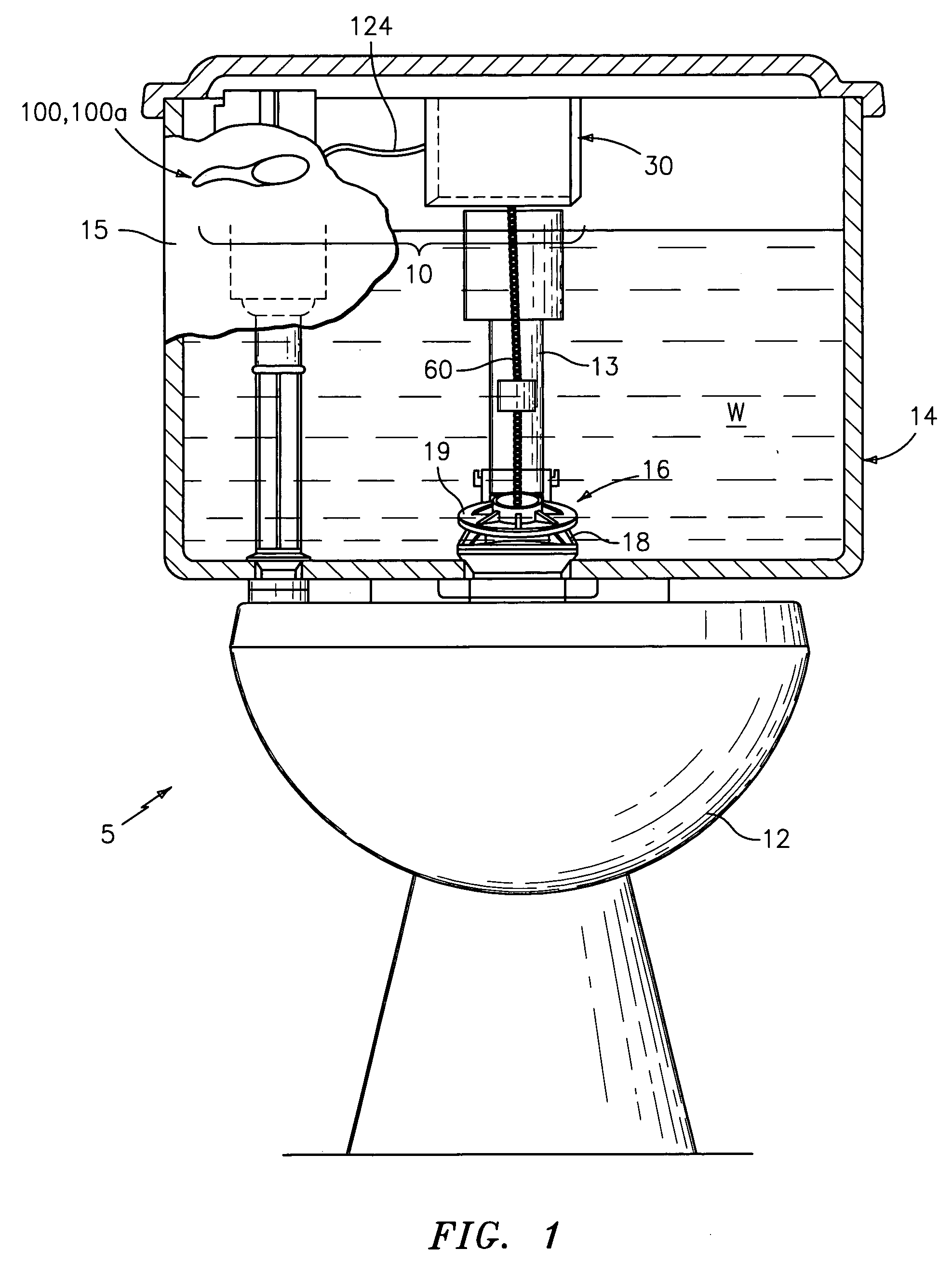
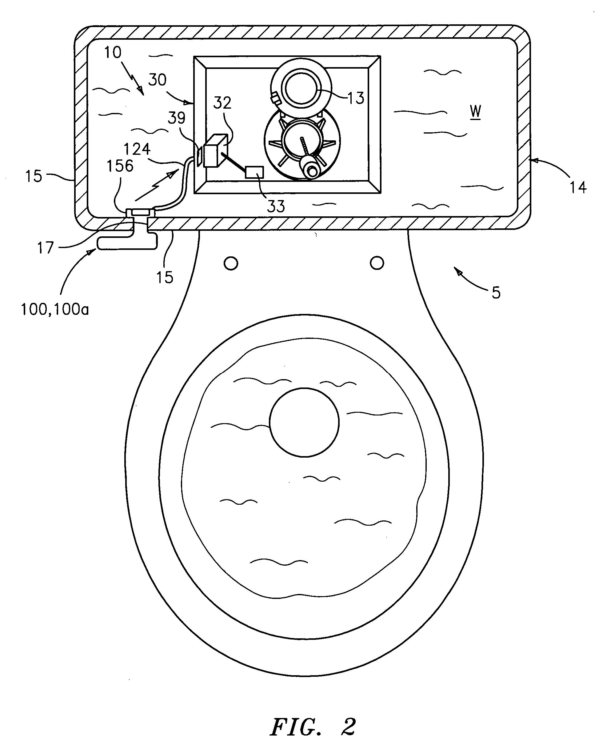
[0030] Reference is first generally made to FIGS. 1 and 2, which illustrate an arrangement, generally indicated at 10, for automatically flushing a toilet of the type that comprises a toilet bowl, generally indicated at 12, and a toilet tank operatively coupled to toilet bowl 12 and generally indicated at 14. The toilet, generally indicated at 5, is of the type that has a flush valve 16 which provides a conduit for water W to flow from toilet tank 14 to toilet bowl 12 when the toilet is flushed. As is quite old in the art, flush valve 16 includes a valve seat 18 and a pivotable flush valve flapper 19 which opens and closes valve 16.

[0031] Autoflush arrangement 10 (“arrangement 10”), in its broadest embodiment, comprises a handle assembly, generally indicated at 100, 100a and a flush valve flapper lifting assembly 30 which is operatively coupled to handle assembly 100, 100a and positioned in toilet tank 14. The main function of assembly 30 is to pivot flush valve flapper 19 from its...


PUM


Abstract

An arrangement for flushing a toilet of the type that comprises a toilet bowl and a toilet tank. In one embodiment, the arrangement comprises a handle assembly comprising a manually actuatable handle that provides a flush signal to the flush valve flapper lifting assembly in response to manual actuation of the handle. In another embodiment, a flush valve actuation assembly, comprising a handle assembly that comprises at least one sensor for detecting the presence of a user in a target area, is mountable in the aperture through a sidewall through which a conventional handle, comprising a lift arm to lift a conventional chain to pivot a conventional flush valve flapper, is mountable.

Description

BACKGROUND OF THE INVENTION [0001] This invention relates generally to automatic flushing systems for toilets, and more particular, to an automatic flushing system for toilets, wherein the toilet is of the type that includes a toilet bowl and an operatively coupled toilet tank. [0002] Toilets comprising a toilet tank / bowl combination with autoflushing capabilities are known, and are the subject of at least two U.S. Patents. For example, U.S. Pat. No. 5,603,127 describes the use of infrared transmitters that transmit an infrared signal to a sensing area directly in front of a toilet bowl to sense the presence of a user in the sensing area. Once the user has left the sensing area, the automatic flushing system will provide a main flush. The '127 patent describes the use of a single housing unit in which both the infrared sensors and the flush motor are positioned. Another example of a toilet with autoflushing capabilities is described in U.S. Pat. No. 5,901,384. A further known system...

Claims


Application Information

Patent Timeline
Patent Type & Authority Applications(United States)
IPC IPC(8): E03D5/09E03D5/10
CPCE03D5/10E03D5/09
Inventor CONTADINI, CARL D.
Owner AMREP IP HLDG
Why Eureka
Try Eureka