
Protection methods, protection circuits and protective devices for secondary batteries, a power tool, charger and battery pack adapted to provide protection against fault conditions in the battery pack

a protection circuit and secondary battery technology, applied in the direction of safety/protection circuits, battery maintenance/service, primary cell maintenance/service, etc., can solve the problems of li-ion batteries that require over-discharge protection, battery deterioration rapidly, and high voltages than described above, so as to prevent internal or external damage to the battery pack or the attached tool

Inactive Publication Date: 2005-04-14
BLACK & DECKER INC
View PDF9 Cites 451 Cited by
  • Summary
  • Abstract
  • Description
  • Claims
  • Application Information

AI Technical Summary

Benefits of technology

[0003] The present invention relates to protection methods, protection circuits and protective devices for rechargeable batteries, to a power tool and charger adapted to provide protection for cells of an attached battery pack, and to a battery pack including protection control therein, each protecting the battery back against various potential fault conditions.

Problems solved by technology

In an over-discharged state, however, the Li-ion batteries deteriorate rapidly, thus Li-ion batteries require over-discharge protection.
However, much higher voltages than described above are required for higher-power electronic devices such as cordless power tools.
Further, as these battery technologies advance, the introduction of lower impedance chemistries and construction styles to develop secondary batteries generating substantially higher output voltages (of at least 18 V and up, for example) may possibly create several additional protection issues.
Such undesirable demagnetization could thus potentially burn up the motor.
For example, a lower impedance electrical source could cause damage to a tool's motor when the tool is held at stall condition.
Higher currents through the motor will increase the likelihood of de-magnetization of the permanent magnets within the tool's motor.
Additionally, start-up of the tool could produce excessive starting currents and cause demagnetization of the motor.

Method used


Image

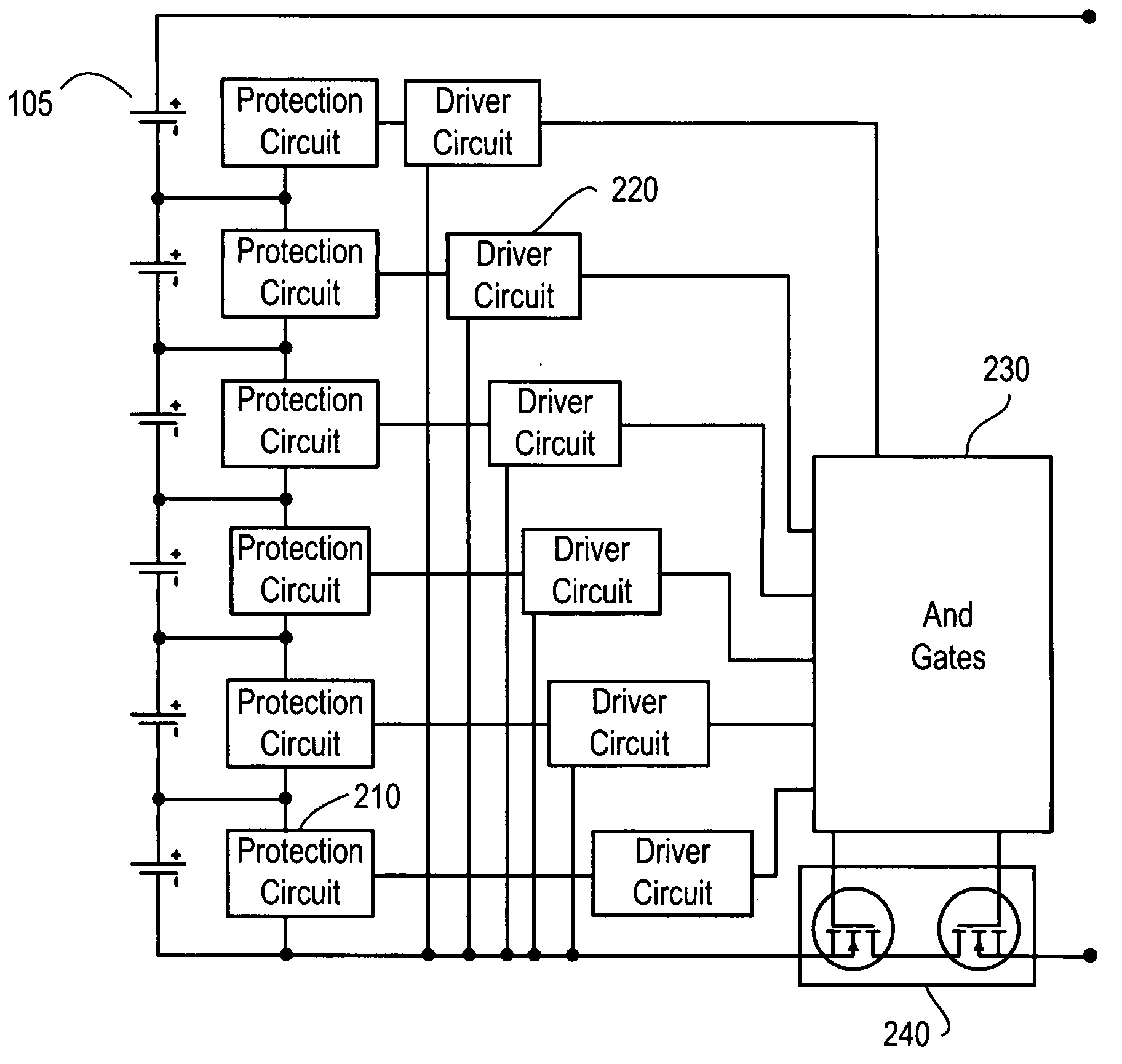
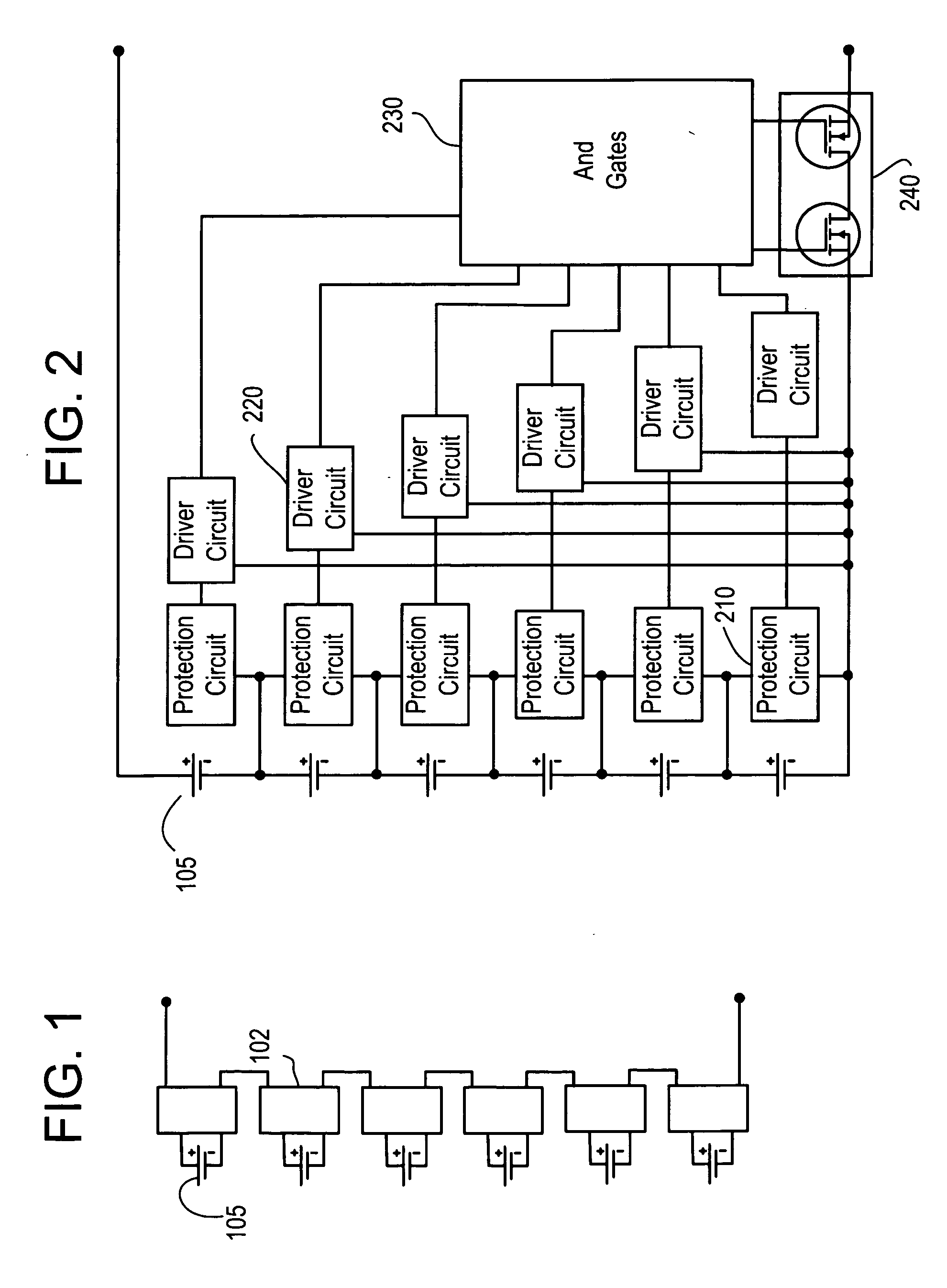
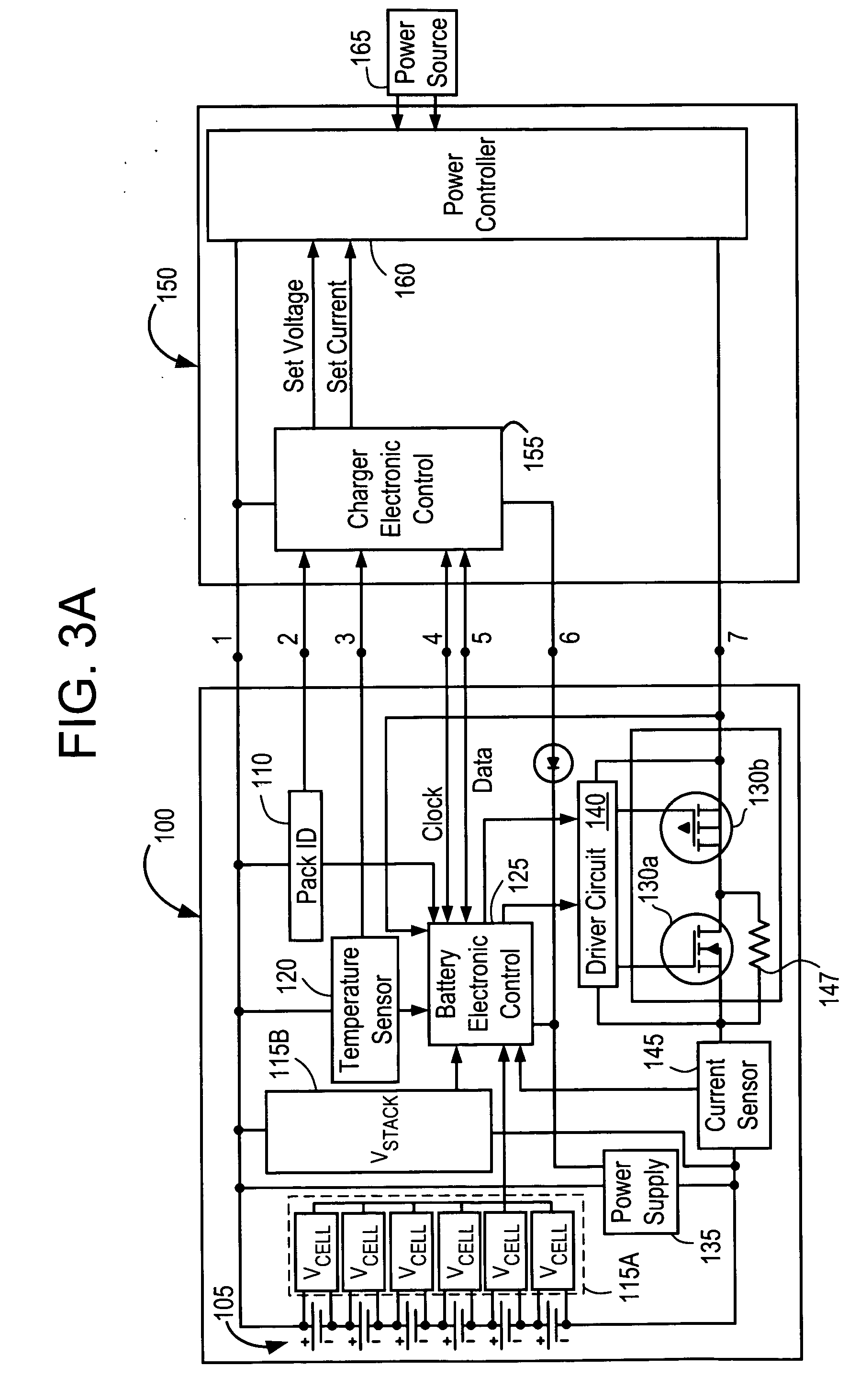
  • Protection methods, protection circuits and protective devices for secondary batteries, a power tool, charger and battery pack adapted to provide protection against fault conditions in the battery pack
  • Protection methods, protection circuits and protective devices for secondary batteries, a power tool, charger and battery pack adapted to provide protection against fault conditions in the battery pack
  • Protection methods, protection circuits and protective devices for secondary batteries, a power tool, charger and battery pack adapted to provide protection against fault conditions in the battery pack

Examples


Embodiment Construction

[0036] With general reference to the drawings, a system of cordless power tools constructed in accordance with the teachings of exemplary embodiments of the present invention is illustrated. Exemplary cordless power tools of the system are shown to include, by way of examples, a circular power saw 10 (FIG. 17), a reciprocating saw 20 (FIG. 18) and a drill 30 (FIG. 19). The tools 10, 20 and 30 each may include a conventional DC motor (not shown) adapted to be powered by a power source having a given nominal voltage rating. In the exemplary embodiments, the tools 10, 20 and 30 may be driven by a removable power source having a nominal voltage rating of at least 18 volts. It will become evident to those skilled that the present invention is not limited to the particular types of tools shown in the drawings nor to specific voltages. In this regard, the teachings of the present invention may be applicable to virtually any type of cordless power tool and any supply voltage.

[0037] With co...


PUM

PropertyMeasurementUnit
voltage ratingaaaaaaaaaa
output voltageaaaaaaaaaa

Abstract

In a cordless power tool system, protection methods, circuits and devices are provided to protect against fault conditions within a battery pack that is operatively attached to a power tool or charger, so as to prevent internal or external damage to the battery pack or attached tool or charger. The exemplary methods, circuits and devices address fault conditions such as over-charge, over-discharge, over-current, over-temperature, etc.

Description

CROSS-REFERENCE TO RELATED APPLICATIONS [0001] This application claims domestic priority under 35 U.S.C. §120 to the following related U.S. Provisional patent applications filed in the United States Patent & Trademark Office: U.S. Provisional Application Ser. No. 60 / 510,128, filed Oct. 14, 2003, and U.S. Provisional Application Ser. No. 60 / 551,803, filed Mar. 11, 2004. The entire contents of the disclosures for each of these provisional applications are incorporated herein by reference.BACKGROUND OF THE INVENTION [0002] 1. Field of the Invention [0003] The present invention relates to protection methods, protection circuits and protective devices for rechargeable batteries, to a power tool and charger adapted to provide protection for cells of an attached battery pack, and to a battery pack including protection control therein, each protecting the battery back against various potential fault conditions. [0004] 2. Description of Related Art [0005] Over the past few years, lithium-ion...

Claims


Application Information

Patent Timeline
Patent Type & Authority Applications(United States)
IPC IPC(8): B25F5/00H01M6/42H01M6/50H01M10/42H01M10/48H01M50/209H01M50/247H01M50/583H02J7/00
CPCB25F5/00Y02T90/12H01M2/1055H01M2/1066H01M2/34H01M2/348H01M6/42H01M10/42H01M10/425H01M10/441H01M10/443H01M10/482H01M10/486H01M10/488H01M2200/106H02J7/0026H02J7/0031B60L2230/12Y02T90/121Y02T10/7088H01M2/1022B60L53/18H02J7/00308H02J7/00309H02J7/0014Y02T10/7072Y02T10/70Y02T90/14Y02E60/10H01M50/213H01M50/581H02J7/00306H02J7/00304H01M50/583H01M50/247H01M2200/00H01M50/574
Inventor CARRIER, DAVEPHILLIPS, STEVEFRANCIS, JEFFREY J.BAILEY, R. ROBYTRINH, DANH THANHSEMAN, ANDREW E. JR.YAHNKER, CHRISTOPHER R.BROTTO, DANIELE C.
Owner BLACK & DECKER INC
Learn More