Method for visually recognizing a droplet, droplet discharge head inspection device, and droplet discharge device

a technology of droplet discharge and visual recognition, which is applied in the direction of printing, other printing apparatuses, etc., can solve the problems of difficult visual recognition of discharged droplets, especially difficult visual recognition of droplets discharged from droplet discharge heads, etc., and achieves the effect of easy visual recognition

Inactive Publication Date: 2005-04-14
SEIKO EPSON CORP
View PDF7 Cites 23 Cited by
  • Summary
  • Abstract
  • Description
  • Claims
  • Application Information

AI Technical Summary

Benefits of technology

[0005] Aspects of the invention can provide a method for visually recognizing a droplet, a droplet discharge head inspection device, and a droplet discharge device that are capable of easily visually recognizing an airborne droplet discharged from a nozzle hole of a droplet discharge head.
[0006] The method for visually recognizing a droplet according to one aspect of the invention can provide visual recognition of an airborne droplet discharged from a nozzle hole included in a droplet discharge head. The method for visually recognizing a droplet can include the following making laser light pass through a slit so as to shape the laser light into a flat-shaped light beam, and irradiating a course of the droplet with the flat-shaped light beam laid out in parallel with the course, so as to illuminate and visually recognize the airborne droplet. The method for visually recognizing a droplet makes it easy to visually recognize an airborne droplet discharged from the nozzle hole included in the droplet discharge head.
[0007] According to the invention, the method for visually recognizing a droplet preferably can include making the laser light pass through a condenser lens before or after passing through the slit. This makes it easy to adjust the width of the light beam of the laser light that intersects the course of the droplet, that is, the length of the course that is irradiated with the laser light.

Problems solved by technology

In the related devices, however, it can be difficult to visually recognize discharged droplets since the diameter of such droplets is too small.
It is particularly difficult to visually recognize droplets discharged from a droplet discharge head with its nozzle looking downward, since the droplets are not disposed to lighting.

Method used


Image

  • Method for visually recognizing a droplet, droplet discharge head inspection device, and droplet discharge device
  • Method for visually recognizing a droplet, droplet discharge head inspection device, and droplet discharge device
  • Method for visually recognizing a droplet, droplet discharge head inspection device, and droplet discharge device

Examples


Embodiment Construction

[0023] A method for visually recognizing a droplet, a droplet discharge head inspection device, and a droplet discharge device according to exemplary embodiments of the invention will now be described with reference to the accompanying drawings.

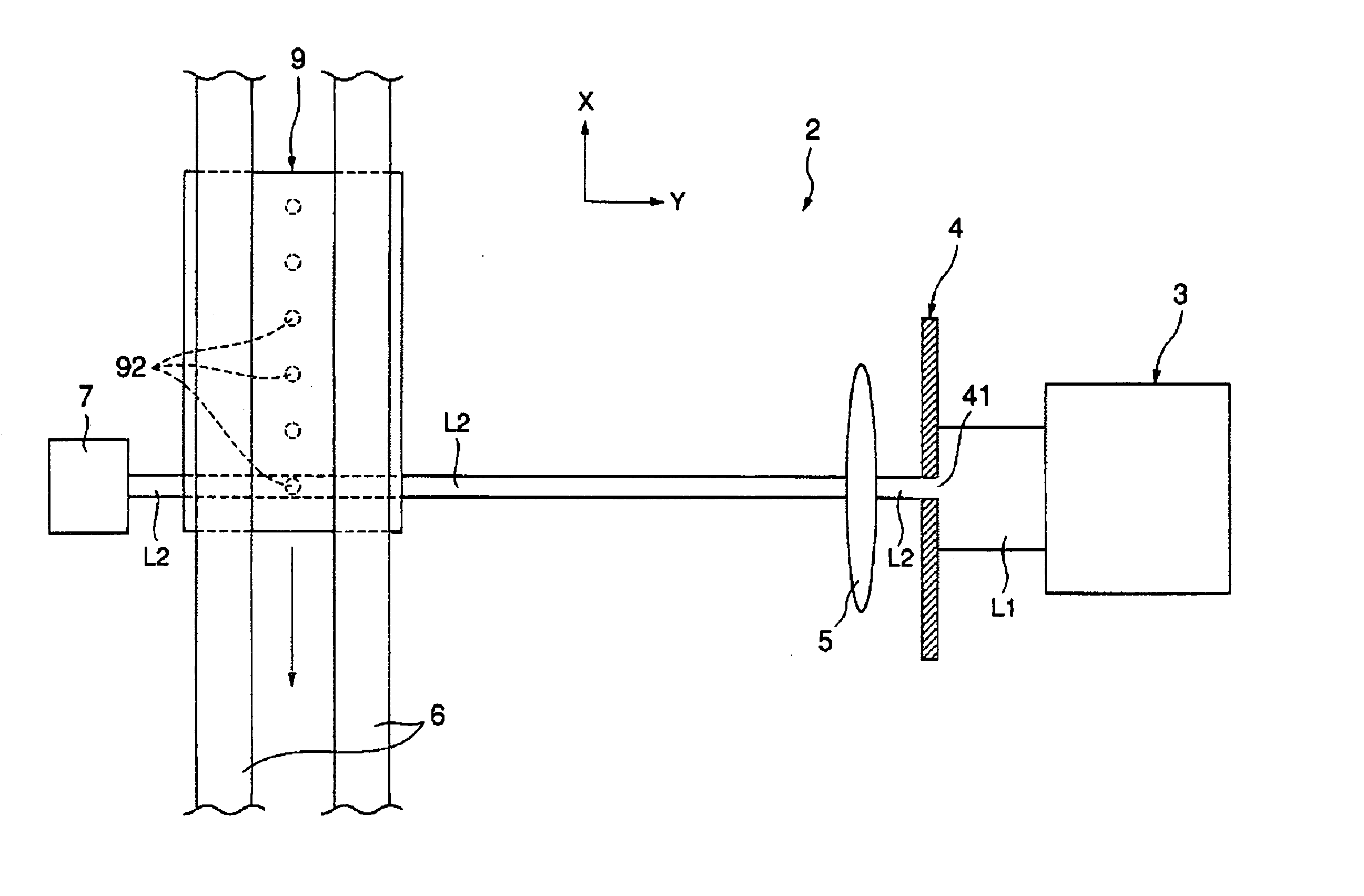
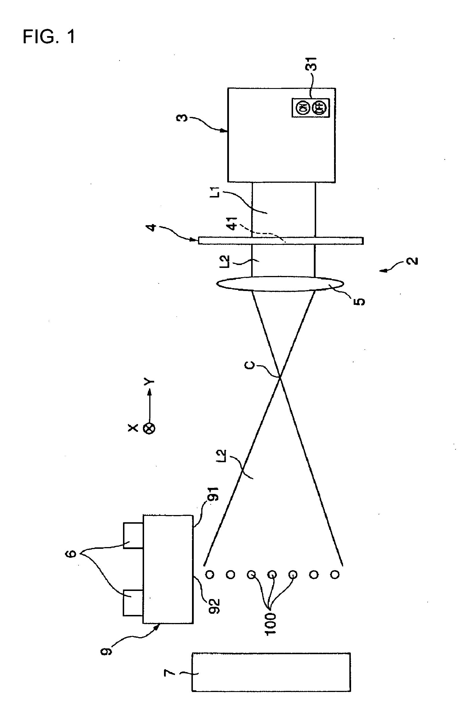
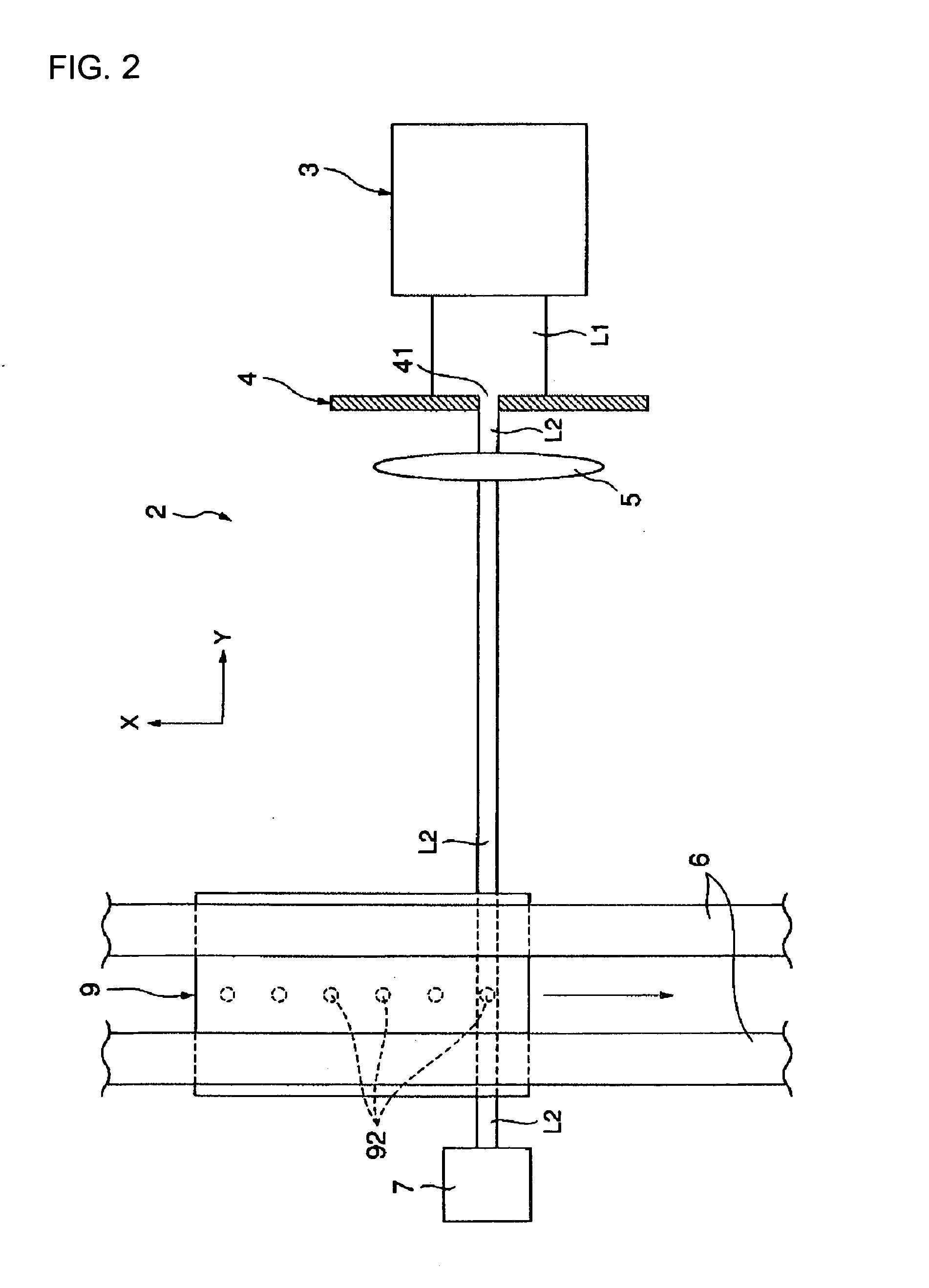
[0024]FIGS. 1 and 2 are a side and plan view, respectively, of the droplet discharge head inspection device of one exemplary embodiment of the invention. FIGS. 3 and 4 are front views of a light shielding plate included in the droplet discharge head inspection device shown in FIGS. 1 and 2, respectively. FIG. 5 is a functional block diagram of the droplet discharge head inspection device shown in FIGS. 1 and 2.

[0025] For convenience, the upper and lower side of FIG. 1 and the vertical and horizontal direction of FIG. 2 are referred to as the upper and lower side and the x- and y-axis direction, respectively, in the description below. A droplet discharge head inspection device 2 shown in the drawings is a device for inspecting the operation ...


PUM


Abstract

Aspects of the invention can provide a method for visually recognizing a droplet, a droplet discharge head inspection device, and a droplet discharge device that are capable of easily visually recognizing an airborne droplet discharged from a nozzle hole of a droplet discharge head. The droplet discharge head inspection device can provide visual recognition of an airborne droplet discharged from a nozzle hole included in a droplet discharge head, and includes a laser light irradiation device that irradiates laser light and a plate member having a slit through which the laser light passes. The laser light is made pass through the slit so as to be shaped into flat-shaped light beams, that is, laser light. With the laser light laid out in parallel with a course of the droplet, the course is irradiated with the laser light. This makes it possible to illuminate and easily visually recognize the airborne droplet.

Description

BACKGROUND OF THE INVENTION [0001] 1. Field of Invention [0002] Aspects of the invention can relate to a method for visually recognizing a droplet, a droplet discharge head inspection device, and a droplet discharge device that are capable of visually recognizing an airborne droplet discharged from a nozzle hole of a droplet discharge head. [0003] 2. Description of Related Art [0004] A related droplet discharge device for discharging droplets on a substrate by using a droplet discharge head having the same mechanism as the inkjet head of ink-jet printers is described, for example, in Japanese Unexamined Patent Publication No. 10-260307. The device is used for industrial purposes, for example, manufacturing a color filter for a liquid crystal display and an organic electroluminescent (EL) display and forming a metal wiring on a substrate. This droplet discharge device and a device for inspecting the performance of the droplet discharge head are expected to allow an operator to visual...

Claims


Application Information

Patent Timeline
Patent Type & Authority Applications(United States)
IPC IPC(8): B41J2/045B41J2/01
CPCB41J2/04561B41J2/04581B41J2/0458B41J2/015B41J29/19
Inventor KOYAMA, MINORU
Owner SEIKO EPSON CORP
Why Eureka
Try Eureka