Electrical junction box

a technology of electrical junction box and bracket, which is applied in the direction of electrical apparatus casing/cabinet/drawer, coupling device connection, installation of lighting conductor, etc., can solve the problems of affecting the smooth operation of locking, interference between the lock section r and the bracket, and the inability to project the bracket from the electrical junction box. , to achieve the effect of smooth locking

a technology of electrical junction box and bracket, which is applied in the direction of electrical apparatus casing/cabinet/drawer, coupling device connection, installation of lighting conductor, etc., can solve the problems of affecting the smooth operation of locking, interference between the lock section r and the bracket, and the inability to project the bracket from the electrical junction box. , to achieve the effect of smooth locking

US20050079740A1Inactive Publication Date: 2005-04-14SUMITOMO WIRING SYST LTD

Image

  • Electrical junction box
  • Electrical junction box
  • Electrical junction box

Examples


Embodiment Construction

[0024] Referring now to the drawings, embodiments of an electrical junction box in accordance with the invention will be described below.

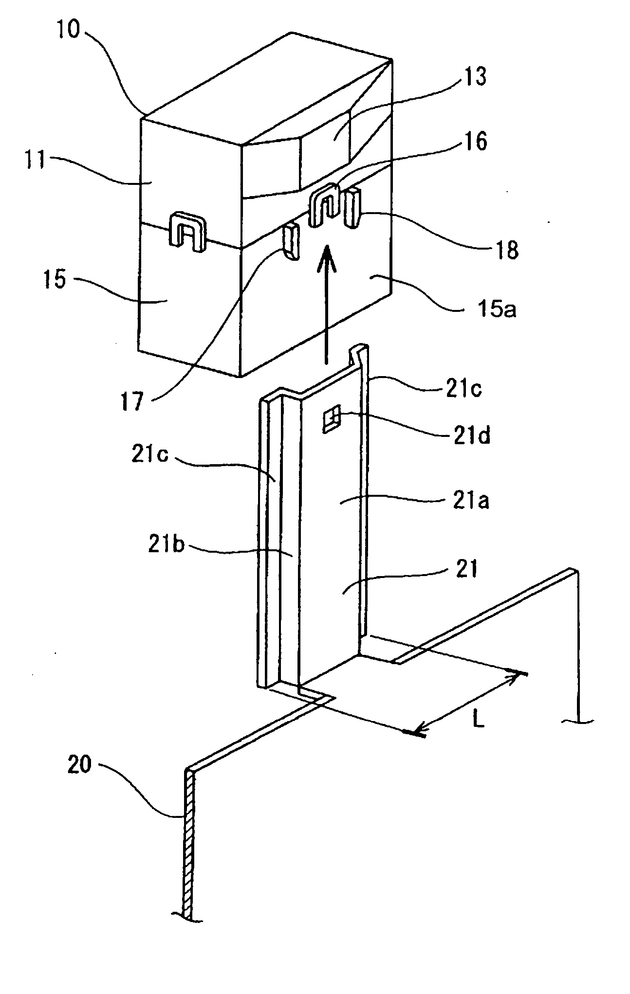
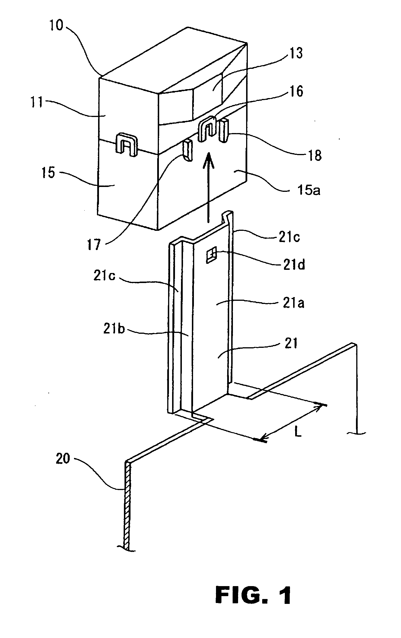
[0025] FIGS. 1 to 5 show an embodiment of the invention. A relay box 10 to be mounted on an automobile vehicle includes a casing comprising a casing body 11 and a lower cover 15 that are made of a resin material, respectively. The casing body 11 and lower cover 15 are jointed and locked to each other. The relay box 10 is secured to a vehicle body 20 through a metallic bracket 21 projecting from the vehicle body 20.

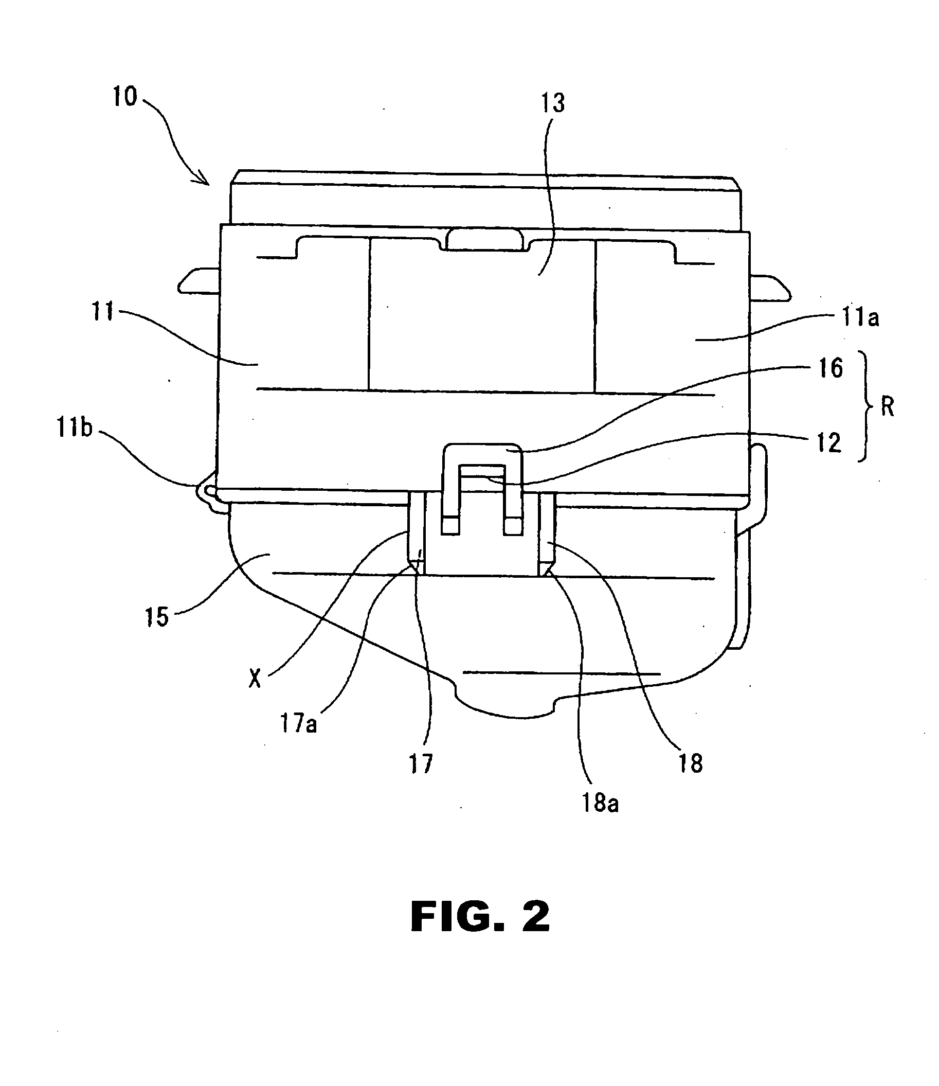
[0026] The casing body 11 is formed into a substantially rectangular configuration and is provided on a front wall 11a (see FIG. 1) at the central lower part with a lock pawl 12. Another lock pawl 11b is provided on a sidewall of the casing body 11 (see FIG. 2) at the lower end. A section 13 being attached to the vehicle body 20 (or vehicle attachment section 13) is provided on the front wall 11a above the lock pawl 12. The vehicle atta...


PUM


Abstract

In an electrical junction box for an automobile vehicle, a casing includes upper and lower casing members. A lock section joints the upper and lower casing members. A vehicle attachment section extends outward from an outer surface of the casing above the lock section. A bracket projecting from a vehicle body is inserted upward into the vehicle attachment section to fix the electrical junction box onto the vehicle body. The electrical junction box comprises a lock protection section including right and left ribs that project from the outer surface of the casing on the opposite sides of the lock section so that the right and left ribs extend to a position higher than the lock section. A distance between the right and left ribs is set to be smaller than a width of the bracket. Then, interference between the bracket and the lock section is prevented upon insertion of the bracket to prevent a casing lock section of an electrical junction box from being damaged when the electrical junction box is secured to a vehicle body.

Description

CLAIM FOR PRIORITY [0001] This invention relates to subject-matter contained in and claims priority to JP 2003-290270, filed on Aug. 8, 2003, the entire disclosure of which is incorporated herein by reference thereto. BACKGROUND OF THE INVENTION [0002] 1. Field of Invention [0003] This invention relates to an electrical junction box for an automobile vehicle and more particularly relates to an electrical junction box that is secured to a vehicle body of an automobile vehicle by inserting a bracket projecting from the vehicle body into a section being attached to the vehicle body that projects from the electrical junction box, thereby preventing interference between the bracket and a lock section for upper and lower casing members of the electrical junction box upon insertion of the bracket. [0004] 2. Description of Related Art [0005] Generally, in order to secure an electrical junction box to a vehicle body of an automobile vehicle, a bolt welded on the vehicle body is inserted into...

Claims


Application Information

Patent Timeline
14 Apr 2005
Publication
US20050079740A1
IPC
H01R13/73; H02G3/08; H05K5/02; H02G3/14
CPC
H01R2201/26; H01R13/73
Inventors
NOJIMA, SHIGERU; MATSUMOTO, MANABU