Door control device, system and method compatible with shielded doors and safety doors

A door control and safety door technology, which is applied in door/window fittings, wing leaf operating mechanism, non-mechanical transmission-operated locks, etc., can solve problems such as door locks not being able to fall, increased space requirements, and doors running out of bounds, etc. Achieve the effect of ensuring smooth falling and locking, reducing installation space requirements and improving safety

Active Publication Date: 2017-04-05
ZHUZHOU CSR TIMES ELECTRIC CO LTD
View PDF7 Cites 1 Cited by
  • Summary
  • Abstract
  • Description
  • Claims
  • Application Information

AI Technical Summary

Problems solved by technology

[0004] The two motors in each unit door in the security door system are controlled by two DCUs, which increases the space requirements and increases the difficulty of the consistency of the two motor steps
At the same time, one unit door requires two DCUs to control, and the corresponding control lines and signal lines also increase, so the space required for installing the DCU also increases accordingly
However, the two DCUs respectively control the two motors in a unit door. It is difficult to compare and compensate the relevant data in real time, so it is difficult to achieve the same pace of the two motors, that is, the synchronization of the two doors in the unit door.
This may cause the situation that the door gap cannot meet the requirements or the door lock cannot fall smoothly when the two doors are closed, that is, one of the doors is in place earlier than the other door. In order to ensure that the middle door gap and closing time meet the requirements, the motor After the door is closed in place, another force will be given to squeeze the door, which will cause the early door to run out of bounds, and the late door will not be in place, so that the door lock cannot fall

Method used


Image

  • Door control device, system and method compatible with shielded doors and safety doors
  • Door control device, system and method compatible with shielded doors and safety doors
  • Door control device, system and method compatible with shielded doors and safety doors

Examples


specific Embodiment

[0074] As a preferred embodiment of the present invention, the door control method also includes the following steps:

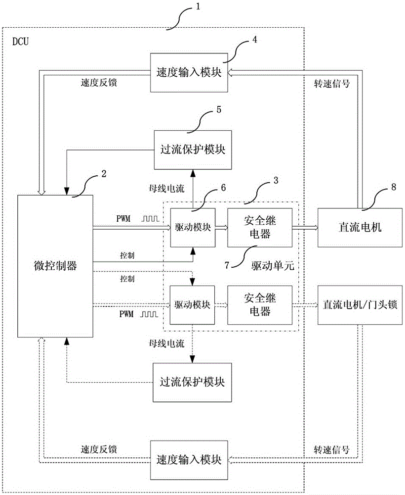
[0075] When the door control system is applied to screen door control or safety door control, the corresponding control program is burned into the microcontroller 2 through the emulator in advance, or the central interface panel 9 is sent to the microcontroller 2 through the CAN bus online for firmware update. At the same time, the corresponding parameters of the door control device controlling the DC motor 8 or the door lock are modified online, and the switching frequency of the upper and lower tubes of the three-phase bridge circuit is set by modifying the PWM wave parameters in the control program.

[0076] Adopting the technical scheme of the door control device, system and method thereof described in the specific embodiments of the present invention that are compatible with screen doors and safety doors can achieve the following technical effects:

[00...


PUM


Abstract

The invention discloses a door control device, system and method suitable for a shield door and a safety door. The device comprises a microcontroller and a drive unit. The drive unit further comprises two sets of drive modules. The microcontroller is connected with one set of drive module of the drive unit and used for controlling an external direct current motor. The microcontroller is further connected with the other set of drive module of the drive unit, used for controlling the other external direct current motor or a door head lock or used for backup, and compatibility of the shield door and the safety door is achieved. The microcontroller outputs PWM waves to the drive modules, and the direct current motors are driven by the drive modules to finish the actions including forward rotation, backward rotation, acceleration, deceleration and constant speed, or the door head lock is driven to finish the opening and closing actions. When the door control device is applied to the safety door, the two paths of direct current motors are the same in step of actions. The door control device, system and method can be suitable for the shielding door and the safety door at the same time, the safety and reliability of the system are improved, and meanwhile the requirement of equipment installing for space is lowered.

Description

technical field [0001] The present invention relates to the field of rail transit equipment, in particular to a door control device, system and method thereof that are compatible with screen doors and safety doors and are widely used in the field of urban rail transit vehicles such as railway locomotives, bullet trains, high-speed trains, and subways. Background technique [0002] There are subway construction projects in many cities across the country, and station screen doors, as an accessory product, can effectively improve the waiting environment, improve the safety of subway operation, and at the same time reduce the operating cost of the subway. Because of different subway lines and different subway stations (open-air platform and underground platform), different door systems may be selected. Open-air platforms usually use safety door systems, while underground platforms usually use screen door systems. The two doors of one unit in the screen door system are driven by...

Claims


Application Information

Patent Timeline
Patent Type & Authority Patents(China)
IPC IPC(8): E05F15/632E05B47/00
Inventor 陈庆贺文余庆酉佳董嗣耀莫伟书
Owner ZHUZHOU CSR TIMES ELECTRIC CO LTD
Why Eureka
Try Eureka