A new type of self-locking mechanism

A self-locking and new technology, applied in the direction of convenient operation, electrical components, electric switches, etc., can solve the problems of lock lever jumping, operation stuck, button self-locking unreliable, etc., to achieve reliable self-locking, smooth operation, avoidance of The effect of jumping stitches

A self-locking and new technology, applied in the direction of convenient operation, electrical components, electric switches, etc., can solve the problems of lock lever jumping, operation stuck, button self-locking unreliable, etc., to achieve reliable self-locking, smooth operation, avoidance of The effect of jumping stitches

CN105374602BActive Publication Date: 2017-07-11NINGBO SUPU ELECTRONICS

Image

  • A new type of self-locking mechanism
  • A new type of self-locking mechanism
  • A new type of self-locking mechanism

Examples


Embodiment Construction

[0037] The following description serves to disclose the present invention to enable those skilled in the art to carry out the present invention. The preferred embodiments described below are only examples, and those skilled in the art can devise other obvious variations.

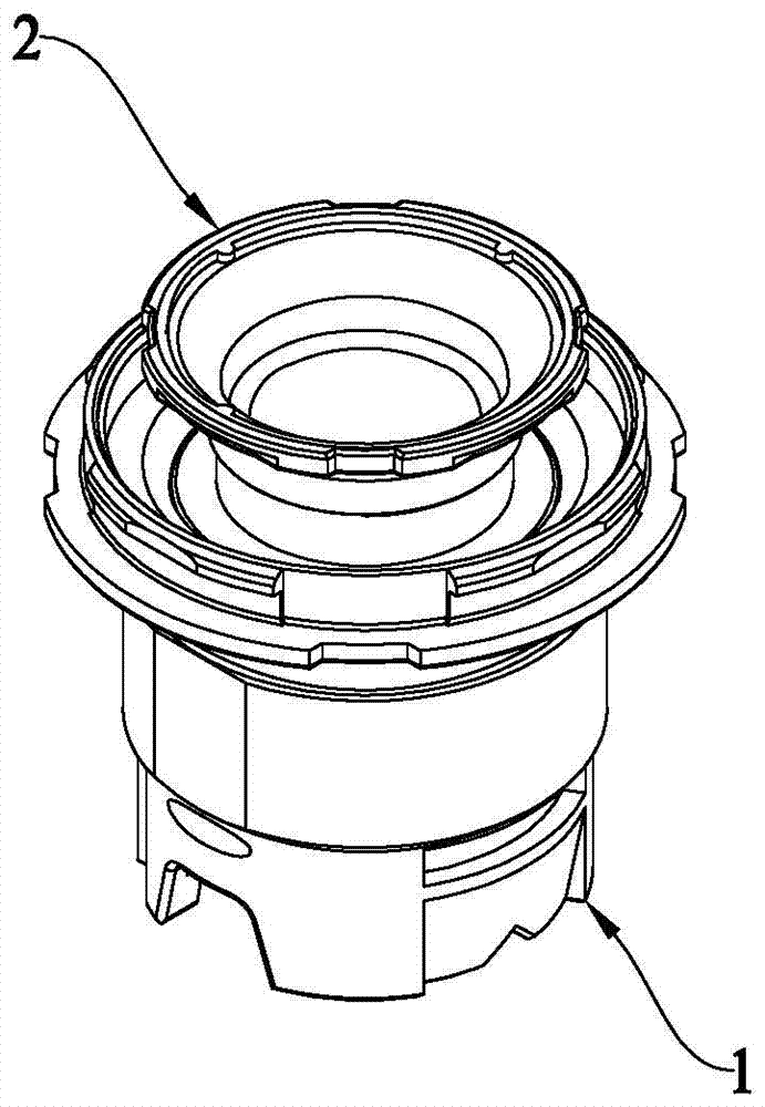
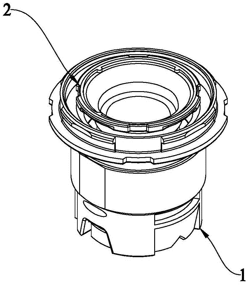
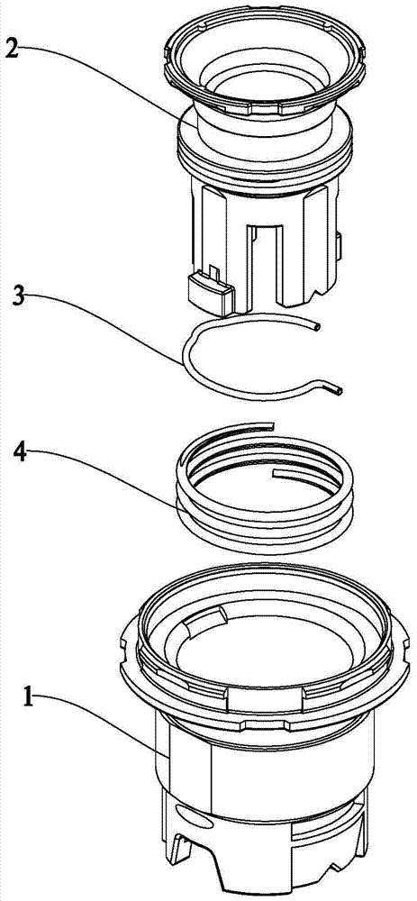
[0038] Such as Figure 1-9 As shown, an embodiment of the present invention includes a sleeve 1, a push rod 2, a lock pin 3 and a reset member 4, the push rod 2 is slidably connected to the inner wall of the sleeve 1, and a reset member is arranged between the sleeve 1 and the push rod 2 4. Specifically, the reset member 4 is a reset spring, the lock pin 3 is a metal wire, and the sleeve 1 is a plastic part.

[0039] Wherein, a groove 11 is provided on the inner wall of the sleeve 1 , and the locking pin 3 slides in the sleeve 1 along with the push rod 2 , and moves in the groove 11 to realize locking and releasing of the locking pin 3 . An annular groove 21 is arranged on the outer wall of the push rod 2...


PUM


Abstract

The present invention provides a novel self-locking mechanism. The novel self-locking mechanism comprises a sleeve, a push rod, a buttonhole stitch and a reset piece. The push rod is slidingly connected with the inner wall of the sleeve, and the reset piece is arranged between the sleeve and the push rod. The novel self-locking mechanism is characterized in that: the buttonhole stitch is arranged on the push rod, the push rod is configured to restrict the axial displacement of the buttonhole stitch and is able to guide the circumference direction displacement of the buttonhole stitch, and a groove is arranged at the inner wall of the sleeve; and the buttonhole stitch slides with the push rod in the sleeve and moves in the groove to realize the locking and releasing of the buttonhole stitch. The novel self-locking mechanism is reliable in self locking, smooth in operation, long in mechanical life, simple in mechanism and convenient in installation.

Description

technical field [0001] The invention relates to the field of self-locking button switches, in particular to a self-locking mechanism of the self-locking button switch. Background technique [0002] The self-locking button switch refers to a switch with a mechanical locking function, which is widely used in command signal equipment. This command signal device is used in machines or electrical equipment to control the operation of machines and equipment. Most pushbutton switches are used to make or break a circuit when pressed, and the state is restored when released. In order to maintain the "pressed" state, a self-locking mechanism is added to the switch. The self-locking mechanism controls the moving contact and the static contact to keep on or off to realize the circuit switching switch, so as to meet the performance requirements. [0003] There are many kinds of self-locking mechanisms, and the most used one is to use a locking pin to enter a groove, and then pass thro...

Claims


Application Information

Patent Timeline
11 Jul 2017
Publication
CN105374602B
IPC
H01H13/56; H01H9/16
CPC
H01H9/16; H01H13/562; H01H2217/018
Inventors
陈浩洋; 林锋