Piezoelectric generator

Inactive Publication Date: 2005-04-21
NAKAGAWA KOZO
View PDF2 Cites 34 Cited by
  • Summary
  • Abstract
  • Description
  • Claims
  • Application Information

AI Technical Summary

Problems solved by technology

However, the levels of power generated were believed to be small static charges.

Method used


Image

  • Piezoelectric generator
  • Piezoelectric generator
  • Piezoelectric generator

Examples


Embodiment Construction

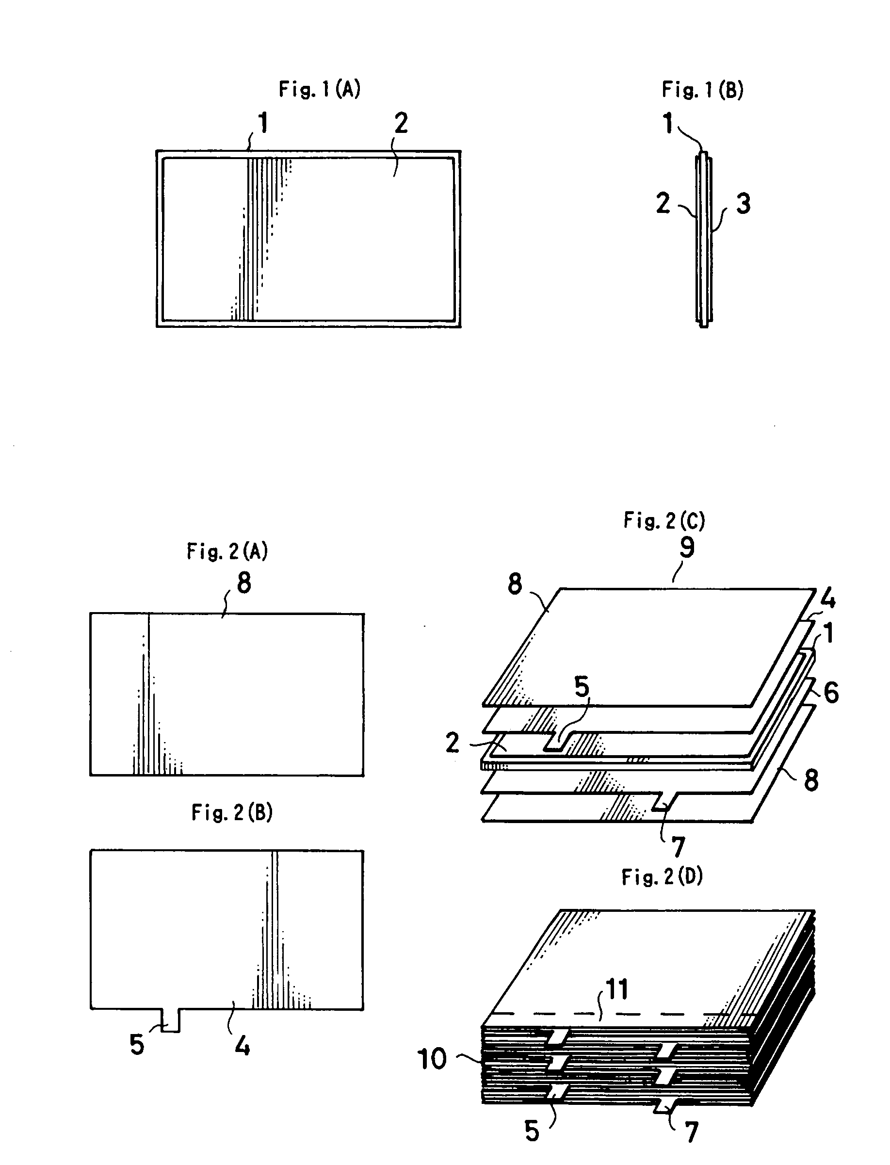
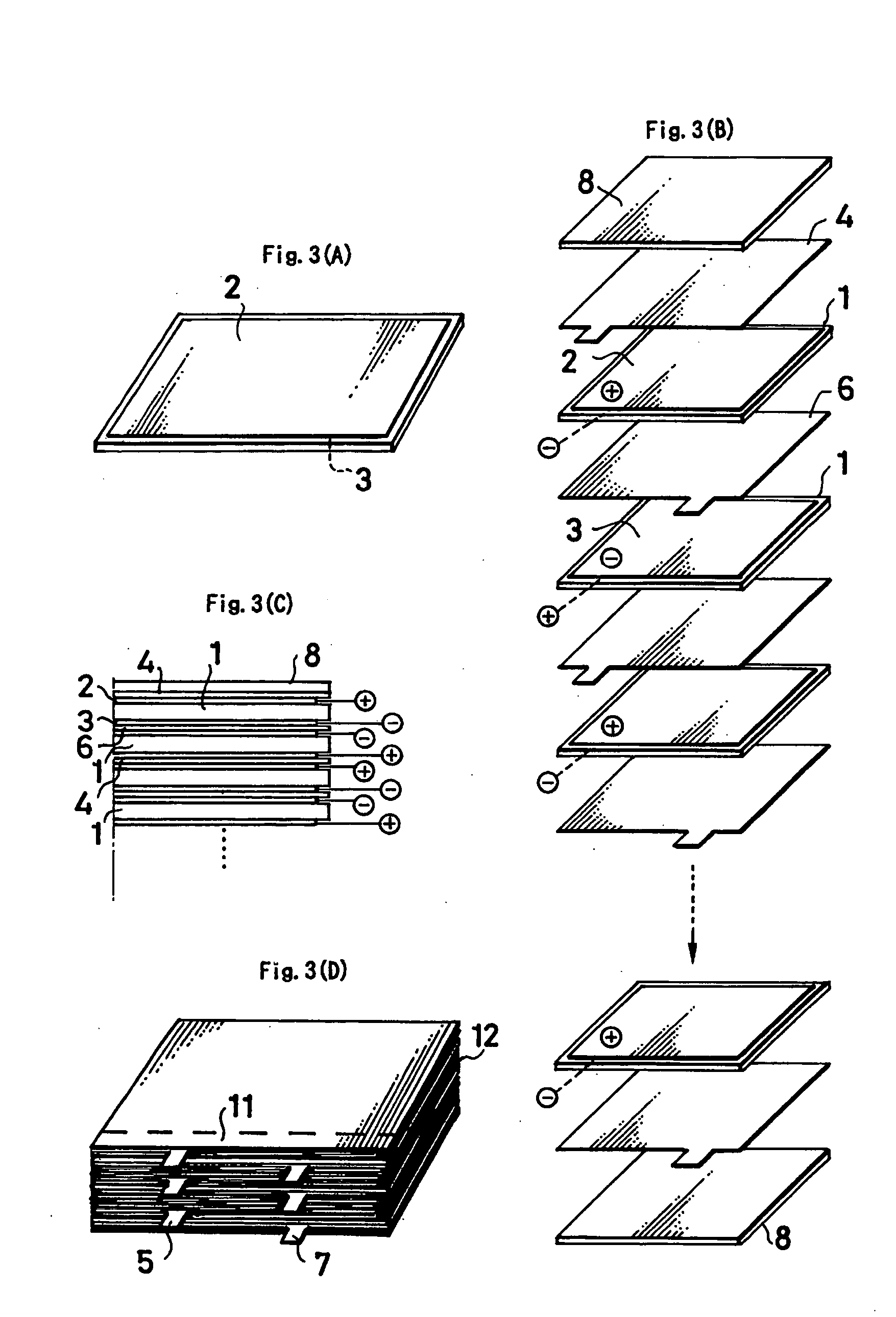
[0013] Embodiments of the present invention are described herein with reference to the drawings. FIGS. 1(A) and 1(B) illustrates a rectangular thin film piezoelectric ceramic element 1 for use in piezoelectric power generation in which metallic electrodes are formed onto both the upper and lower surfaces of the piezoelectric ceramic element 1 by baking or plating a metal having good conductance or the like to a uniform thickness and a configuration closely resembling the outline of the piezoelectric ceramic element in the proximity of but inside thereof. The electrode on the upper surface is designated as (+) electrode 2 and the electrode on the lower surface is designated as (−) electrode 3.

[0014] The rectangular thin film piezoelectric ceramic element 1 is so thin that it tends to flex.

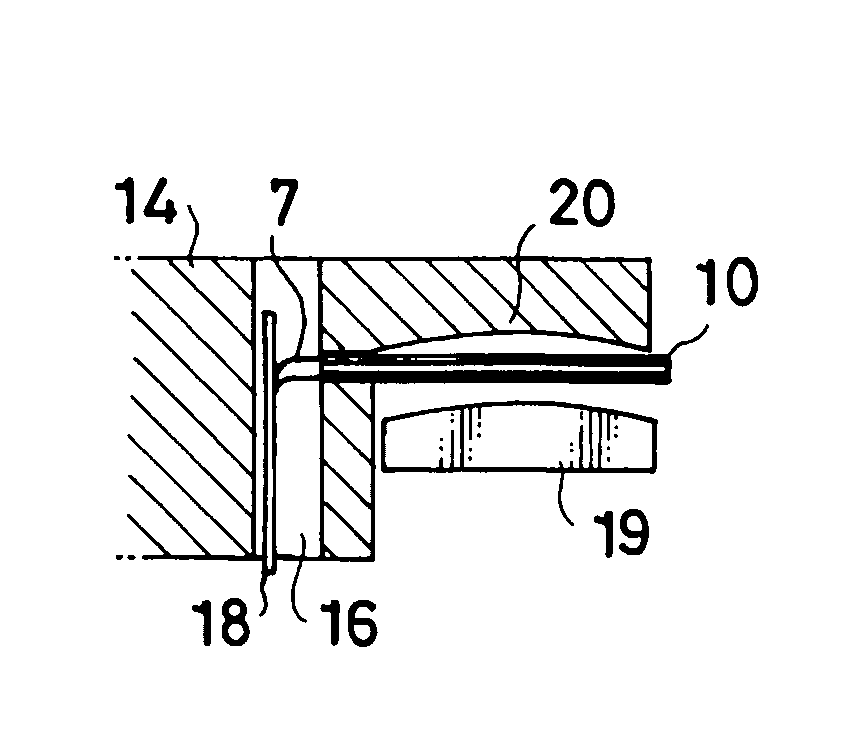
[0015] As illustrated in FIGS. 2(A) through 2(D), a rectangular thin piezoelectric ceramic element 1 is made into an element set 9 as shown more specifically in FIG. 2(C) by attaching a (−) electr...


PUM


Abstract

A power generation and transmission system of conventional technology has public hazard issues associated with long distance transmission of water power, thermal power, and atomic power accompanied by energy losses. A power generation method utilizing natural energy such as solar, wind, and the like, also has a problem in scaling and stability of power generation capacity. The present invention utilizes a large number of piezoelectric elements and controls electric discharges to provide power in a stable and highly efficient manner. It provides a power generation system according to demand of factories in a hazard free and transmission system free manner.

Description

TECHNICAL FIELD [0001] The present invention relates to an electric power generator and more particularly to a piezoelectric ceramic electric power generator. RELATED ART [0002] The ability of a piezoelectric ceramic to generate power upon an impact or application of a similar mechanical force thereto is known to the public. However, the levels of power generated were believed to be small static charges. PROBLEMS TO BE SOLVED [0003] Lately, as environmental contamination is a serious social concern, energy conservation type power generators such as wind mill power generators or fuel cells have been rigorously developed. A piezoelectric ceramic can obviously generate electric power, even though its output is limited to a very low level. A piezoelectric ceramic capable of generating electricity of a commercial grade would greatly contribute to society. [0004] The present invention is based on experiments conducted repeatedly proving that a piezoelectric ceramic has the capacity of une...

Claims


Application Information

Patent Timeline
Patent Type & Authority Applications(United States)
IPC IPC(8): H01L41/083H01L41/113
CPCH01L41/083H02N2/18H01L41/1136H10N30/50H10N30/306
Inventor TSUJIURA, MICHIO
Owner NAKAGAWA KOZO
Why Eureka
Try Eureka